
Scanning microscopy, fluorescence detection, and laser beam positioning

a scanning microscopy and fluorescence detection technology, applied in the field of improved data acquisition techniques, can solve the problems of limiting the permissible intensity of the beam, increasing the waste of laser photons, and limiting the beam's intensity

Inactive Publication Date: 2006-05-23
OVERBECK JAMES W
View PDF46 Cites 56 Cited by
  • Summary
  • Abstract
  • Description
  • Claims
  • Application Information

AI Technical Summary

Benefits of technology

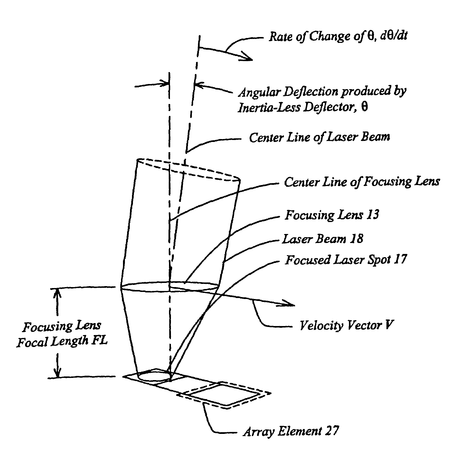
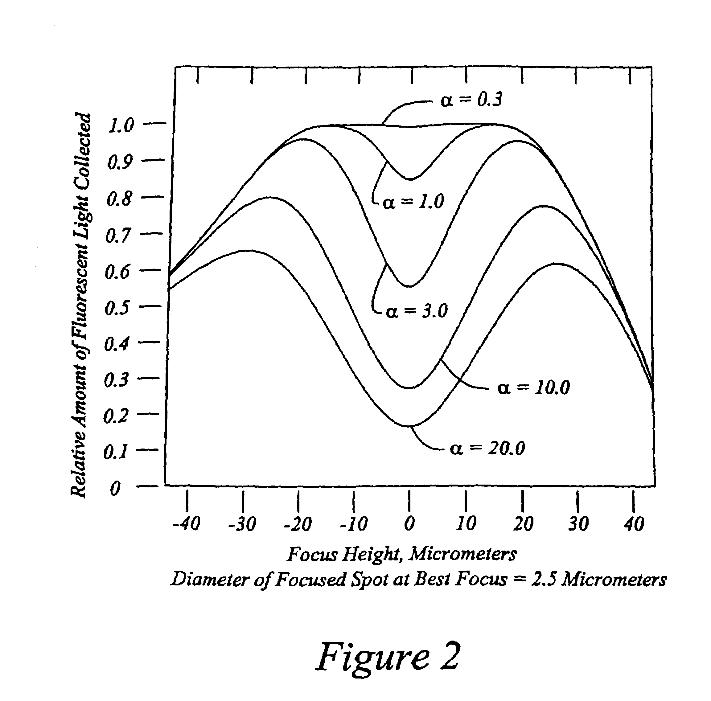
This approach enhances fluorescence detection efficiency, reduces fluorophore saturation, and allows for faster data acquisition from high-density micro-arrays by optimizing laser spot size and dwell time, thereby improving the signal-to-noise ratio and reducing the impact of feature size and energy sensitivity.

Problems solved by technology

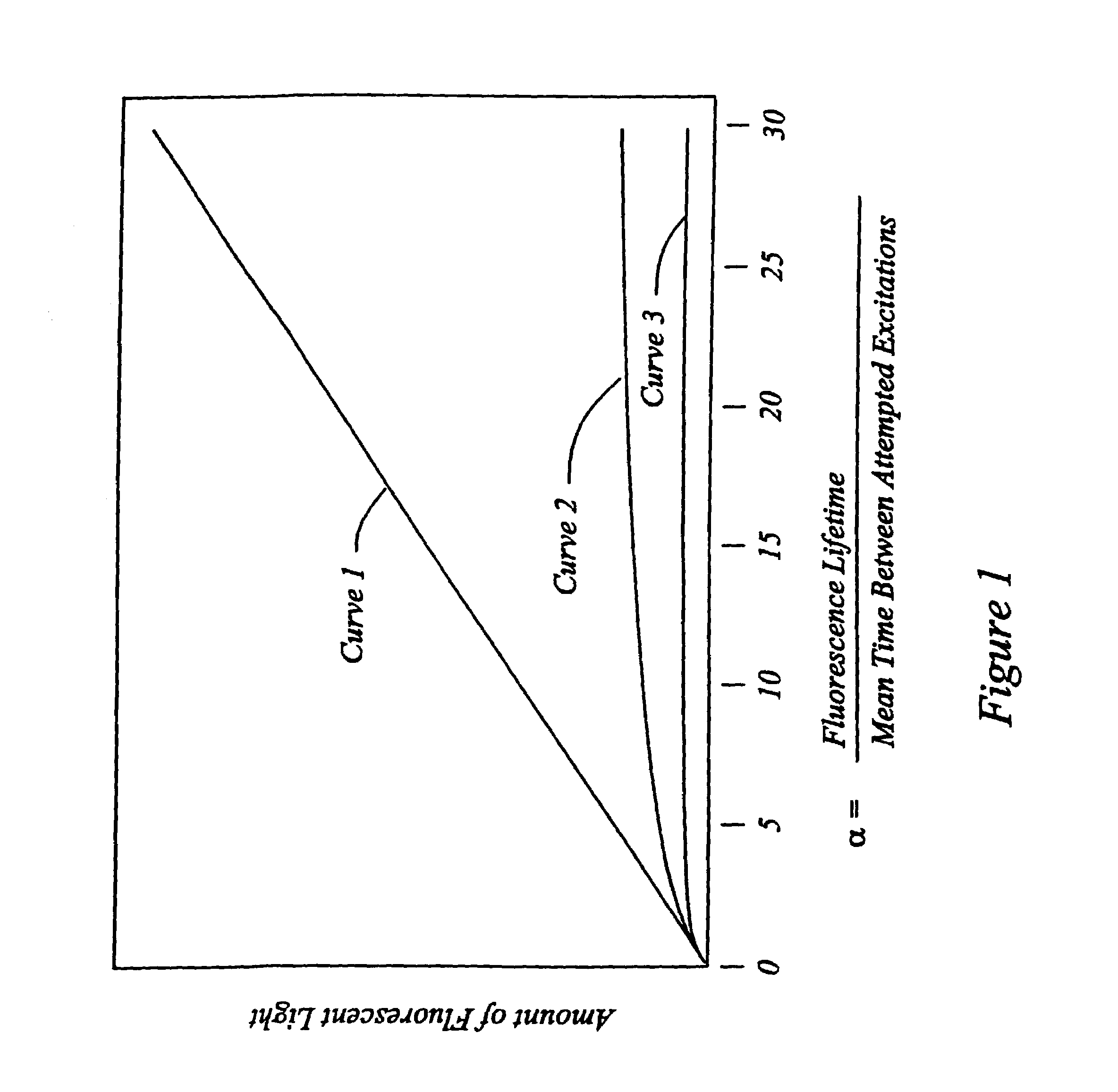
However, in the very important case of use of fluorescent molecules as tags (“fluorophores”), a limit is encountered because of saturation characteristics of the fluorophore, i.e. there is delay between the time of excitation of the fluorophore by an incident photon and the time of its emitting its fluorescing photon, during which, another photon incident on that fluorophore can have no effect and would be wasted.
The fragility or energy-sensitivity of biological material itself can also limit the permissible intensity of the beam.
In these cases, the simultaneous reduction of feature size and laser spot size results in a greatly increased waste of laser photons, and a decreased amount of fluorescent light per feature, hence scanning is forced to proceed at slower rate than desired.
Excessive heat may result in unwanted damage or unwanted chemical reactions.

Method used


Image

  • Scanning microscopy, fluorescence detection, and laser beam positioning
  • Scanning microscopy, fluorescence detection, and laser beam positioning
  • Scanning microscopy, fluorescence detection, and laser beam positioning

Examples


Embodiment Construction

OF OTHER EMBODIMENTS

[0133]In biological applications in which an array element is deposited as a droplet of liquid, the locations of the individual array elements are not precisely controllable. Therefore it becomes desirable to measure the location of each array element. Measuring such locations has been a byproduct of previous commercial methods of scanning biological arrays, because those methods produce a high resolution picture of the entire array. This high resolution picture has come at a high cost in throughput, and has involved the use of a small focused laser spot, which in turn stimulates the problem of fluorophore saturation that has been overcome by the present invention. According to another aspect of the present invention, provision is included for a preliminary scan of the array, performed rapidly, for the purpose of locating the array elements, spending a small fraction of the time, in an example approximately 20 microseconds per array element, 20 microseconds being...


PUM


Abstract

High speed, wide area microscopic scanning or laser positioning is accomplished with an inertia-less deflector (for example an acousto-optic or electro-optic deflector) combined with a high speed wide area microscopic scanning mechanism or laser positioner mechanism that has inertia, the motion of the inertia-less deflector specially controlled to enable a focused spot to stabilize, for example to stop and dwell or be quickly aimed. It leads to improved data acquisition from extremely small objects and higher speed operation. In the case of fluorescence reading of micro-array elements, dwelling of fluorophore-exciting radiation in a spot that is relatively large enables obtaining the most fluorescent photons per array element, per unit time, a winning criterion for reducing fluorophore saturation effects. The same inertia-less deflector performs stop and dwell scanning, edge detection and raster scans. Automated mechanism for changing laser spot size enables selection of spot size optimal for the action being performed.

Description

[0001]This application claims priority under 35 USC §119(e)(1) to U.S. Provisional Application Ser. No. 60 / 333,795, filed on Nov. 28, 2001, the entire contents of which are hereby incorporated by reference.COMPUTER PROGRAM LISTING APPENDIX[0002]A Computer Program Listing Appendix is included at the end of this patent specification and on a computer disc. It is readable by the Microsoft Windows operating system and contains six C language computer programs in ASCII text form, as follows:[0003]NameSize in BytesDate of Creation of CDfs_algorithm.c14286Oct. 30, 2001fs_fast_algorithm.c21417Oct. 30, 2001fs_fast.c18549Oct. 30, 2001fs_main.c1412Oct. 30, 2001fs_support.c7922Oct. 30, 2001simul_motion.c10084Oct. 30, 2001[0004]The entire contents of this Computer Program Listing Appendix are hereby incorporated by reference.BACKGROUND[0005]This invention concerns improved data acquisition techniques in wide field, high speed laser microscopy, improvement in the life science specialty of bioinfo...

Claims


Application Information

Patent Timeline
Patent Type & Authority Patents(United States)
IPC IPC(8): G02B26/08G02B21/00G02B21/16G02B21/18
CPCG02B21/002G02B21/0048G02B21/18G02B21/0076G02B21/0096G02B21/16G02B21/006G01N21/6458
Inventor OVERBECK, JAMES W.
Owner OVERBECK JAMES W
Learn More