Surge protector assembly with ground-connector status indicator circuitry

Active Publication Date: 2006-05-23
ILLINOIS TOOL WORKS INC
View PDF17 Cites 25 Cited by
  • Summary
  • Abstract
  • Description
  • Claims
  • Application Information

AI Technical Summary

Benefits of technology

[0008]Accordingly, it is a general object of the present invention to provide an improved surge protector assembly for use in

Problems solved by technology

As is generally known to those skilled in the telecommunications industry, modern telecommunication equipment is susceptible to transient surges such as those caused by lightning strikes and other voltage/current surges on the transmission lines.
Therefore, an installer or user was unable to determine whether surge protector wa

Method used


Image

  • Surge protector assembly with ground-connector status indicator circuitry
  • Surge protector assembly with ground-connector status indicator circuitry
  • Surge protector assembly with ground-connector status indicator circuitry

Examples


second embodiment

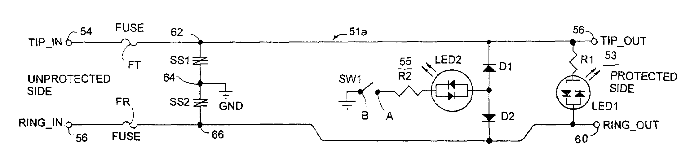
[0043]In FIG. 10, there is depicted a schematic circuit diagram of a surge protector network 51b which is substantially identical to the surge protector network 51a of FIG. 9 just described in detail above, except that the fuses FT, FR have been replaced with a pair of positive temperature coefficient devices PTC1 and PTC2 and a diode bridge rectifier formed of diodes D3–D6 has been added between the voltage suppressors SS1, SS2 and the internal nodes 62, 66 for use in applications where a high-speed, high-frequency of operation is required. Except for these differences, the remaining components or elements of the protection-operational status indicator circuitry 53 and the ground-connected status indicator circuitry 55 and their electrical interconnections are identical to FIG. 9.

third embodiment

[0044]In FIG. 11, there is depicted a schematic circuit diagram of a surge protector network 51c which is also substantially identical to the surge protector network 51a of FIG. 9, except that the fuses FT, FR have been replaced with a pair of positive temperature coefficient devices PTC1 and PTC2. Except for this difference, the remaining components or elements of the protection-operational status indicator circuitry 53 and the ground-connected status indicator circuitry 55 and their electrical interconnections are identical to FIG. 9.

[0045]FIG. 12 is a schematic circuit diagram of an alternate embodiment of the ground-connected status indicator circuitry 55a which is quite similar to the indicator circuitry 55 of FIG. 9, except that the rectifier diodes D1 and D2 have been eliminated. FIG. 13 is a schematic circuit diagram of a second alternate embodiment of the ground-connected status indicator circuitry 55b which is substantially identical to the indicator circuitry 55 of FIG. 9...


PUM


Abstract

There is provided a surge protector assembly for use with a 66-M type terminal connector block having a plurality of parallel rows of opposed terminals which are laterally spaced apart from each other. The surge protector assembly includes a housing module formed of co-mating front and back halves. A miniature printed circuit board is disposed within the housing module. Surge protector devices, a protector-operational status indicator circuitry, and a ground-connected status indicator circuitry are disposed on the miniature printed circuit board. A plurality of tip/ring terminal contacts are disposed within a lower portion of the housing module for mating with corresponding ones of the opposed terminals of the 66-M type terminal connector block.

Description

BACKGROUND OF THE INVENTION[0001]1. Field of the Invention[0002]This invention relates generally to surge protection devices for protecting telephone / data communications related equipment from power and transient surges. More particularly, it relates to an improved surge protector assembly for protecting telecommunications equipment from power and transient surges occurring on the tip and / or ring conductors of transmission lines connected thereto. Specifically, the surge protector assembly of the instant invention includes a two-piece interfitting housing module of a unique construction and a miniature printed circuit board for mounting surge protector devices, a protector-operational status indicator circuitry, and a ground-connected status indicator circuitry all disposed within the housing module.[0003]2. Description of the Prior Art[0004]As is generally known to those skilled in the telecommunications industry, modern telecommunication equipment is susceptible to transient surge...

Claims


Application Information

Patent Timeline
IPC IPC(8): H02H1/00H01C7/12H01T4/06H04M3/18H04Q1/14H05K1/02H05K1/18H05K3/34
CPCH01C7/123H01T4/06H04M3/18H04Q1/146H02H9/042H05K1/0257H05K1/18H05K3/3405H05K2201/1034H04Q2201/12
Inventor SATO, NICHOLASKIELIAN, SLAWOMIROGUZ, ARIFTRUESDALE, BRIAN J.FOURNIER, JAMESHALLIDAY, RICHARD T.
Owner ILLINOIS TOOL WORKS INC
Why Eureka
Try Eureka