
Optical information recording method and apparatus, and recorded medium where optical information recording control program is recorded

Inactive Publication Date: 2006-05-23
TAIYO YUDEN KK
View PDF10 Cites 13 Cited by
  • Summary
  • Abstract
  • Description
  • Claims
  • Application Information

AI Technical Summary

Benefits of technology

[0015]It is an object of the present invention to provide an optical information recording method and device which can record information on an information recording surface of an optical information recording medium with a direction of irradiating laser light kept stable even if an inclination or the like is caused in the information recording surface.
[0016]It is also an object of the present invention to provide a recording medium having an optical information recording control program recorded thereon so that information can be recorded on the information recording surface of an optical information recording medium with a direction to irradiate the laser light kept uniform even if information recording surface is inclined.

Problems solved by technology

Mostly, the inclination of the information recording surface is not uniform and becomes large gradually from the inner circumference toward the outer circumference of the optical disc.
Therefore, the pit size becomes small, and jitter becomes worse when the information is reproduced.
However, the mechanism to incline the optical pickup according to the tilt angle θ is complex, and the device costs a great deal.

Method used


Image

  • Optical information recording method and apparatus, and recorded medium where optical information recording control program is recorded
  • Optical information recording method and apparatus, and recorded medium where optical information recording control program is recorded
  • Optical information recording method and apparatus, and recorded medium where optical information recording control program is recorded

Examples


Embodiment Construction

[0170]One embodiment of the present invention will be described with reference to the accompanying drawings.

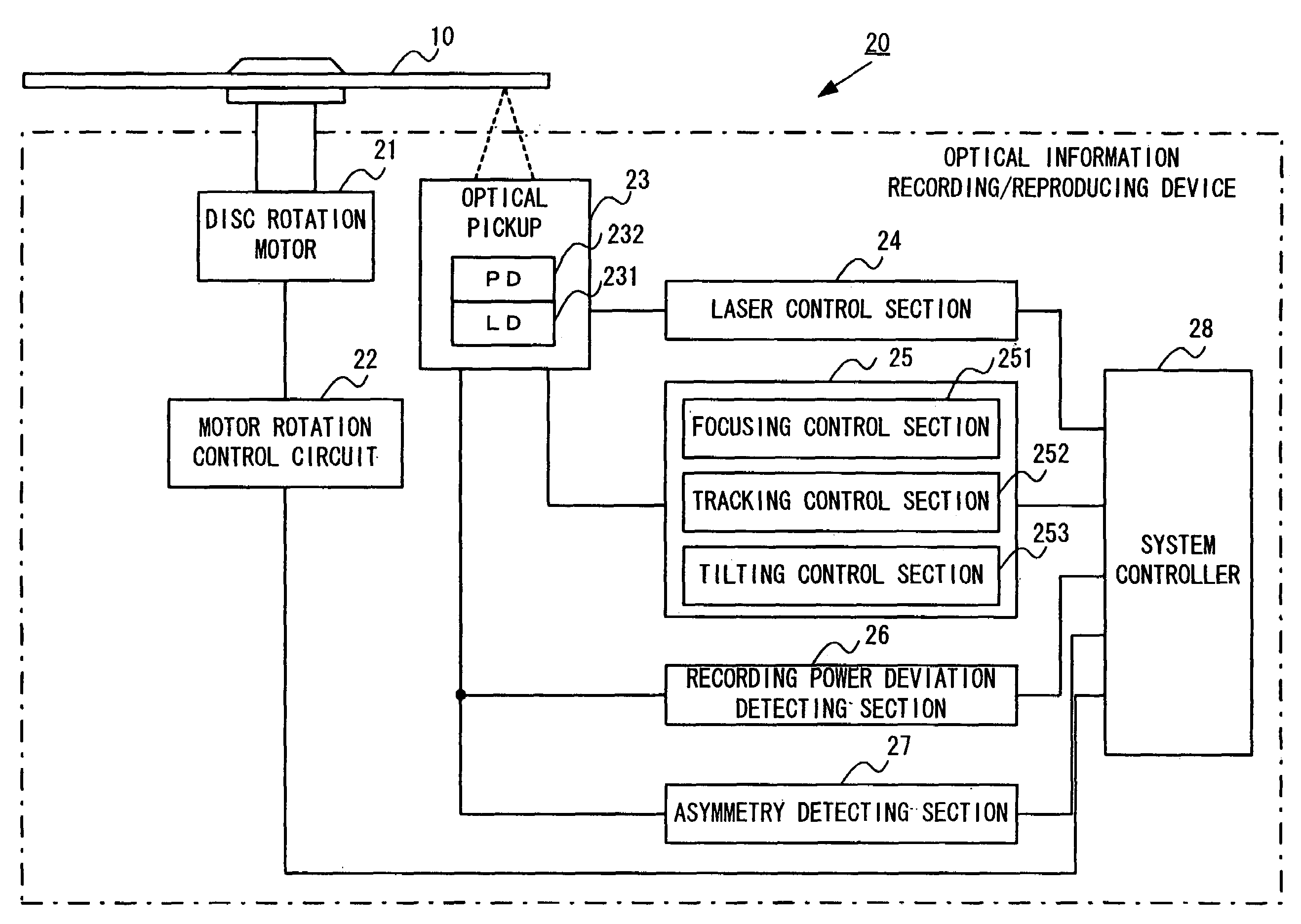
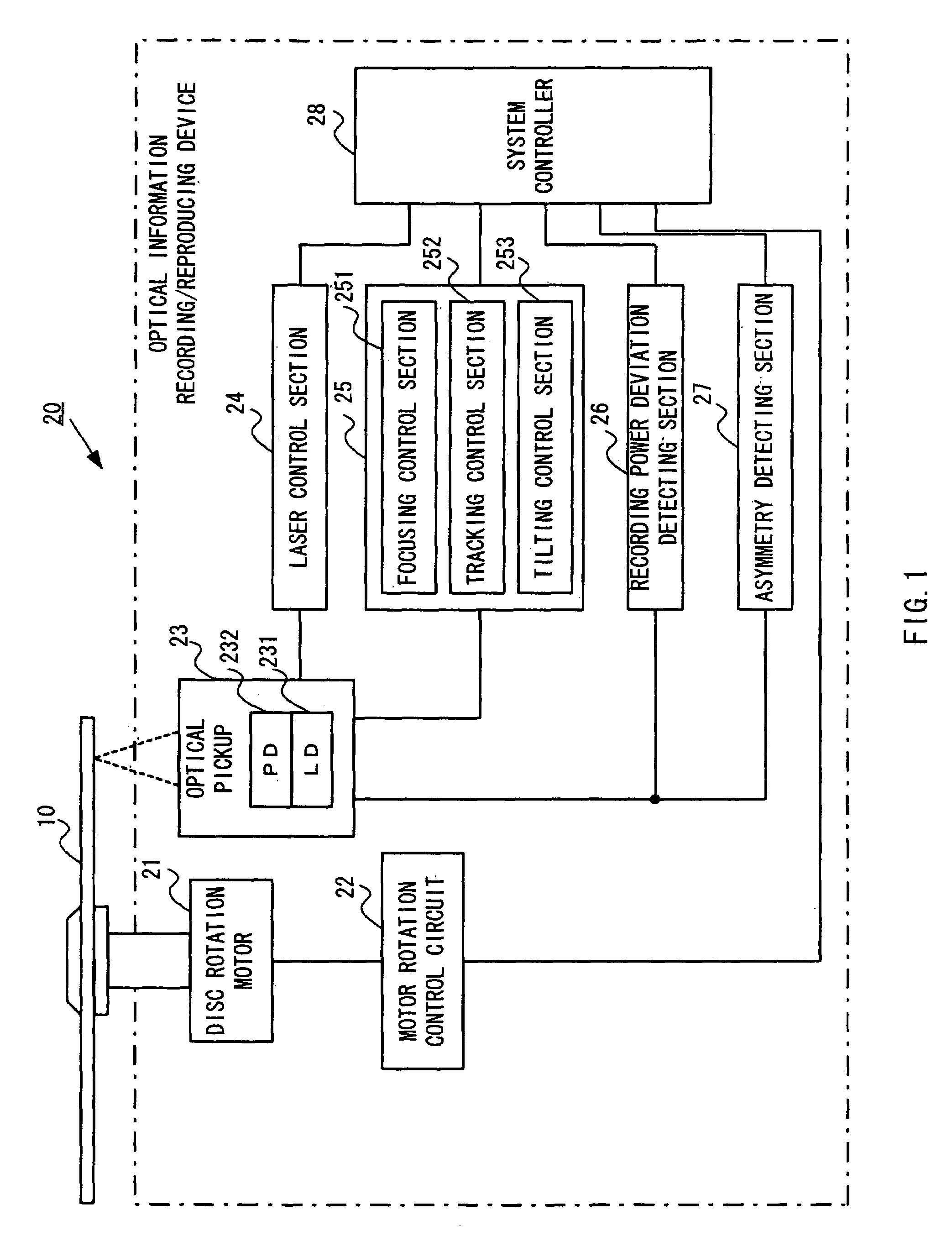
[0171]FIG. 1 is a block diagram showing a main electric circuit of the optical information recording device according to one embodiment of the present invention. This embodiment describes a structure of the device for a known DVD-R as a write once type optical information recording medium. The device for CD-R which is also known as a write once type optical disc has almost the same structure.

[0172]In FIG. 1, 10 is a write once type optical disc, and 20 is an optical information recording device.

[0173]The optical information recording device 20 has disc rotation motor 21, motor drive control circuit 22, optical pickup 23, laser control section 24, servo control section 25, recording power deviation detection section 26, asymmetry detection section 27, system controller 28 and the like.

[0174]The optical disc 10 has grooves previously formed on its recording area (recording track...


PUM


Abstract

An optical information recording method and a device which can record information with a laser light irradiating direction kept constant even if an information recording surface of an optical information recording medium is inclined and, a recording medium having a program therefor recorded thereon are provided. When performing OPC, a relational expression between a recording power and asymmetry (a standard expression), a relational expression between a differential light intensity value and a recording power (a first detection expression), a relational expression between a recording power and a difference between a differential light intensity value and a reflected light amount ratio (a second detection expression), a relational expression between a reflected light amount ratio and a recording power (a third detection expression), a differential light intensity value with which optimum asymmetry can be obtained, a recording power, a reflected light amount ratio and the like are determined and stored. When information is actually recorded, the above expressions are used to correct the recording power so as to obtain optimum asymmetry at all times, whereby a decreased portion of the irradiated light amount per unit area caused with the inclination of the information recording surface can be corrected without correcting the irradiating direction of the laser light.

Description

[0001]This application is a 371 of PCT / JP00 / 02828 Apr. 28, 2000.TECHNICAL FIELD[0002]The present invention relates to an optical information recording method and a device and also a recording medium on which an optical information recording control program is recorded.BACKGROUND ART[0003]Conventionally, there is used a technology to record a large volume of information on an optical information recording medium, e.g., an optical disc such as a write once type optical disc (CD-R). And, the technology for recording information at 2–6X speed or a faster recording speed is coming into general use in recent years.[0004]When recording information on an optical disc, based on a digital signal of digitized information to be recorded, pulse-shaped laser light is irradiated from an optical pickup to the rotating optical disc to form pits.[0005]For example, to form pits on the optical disc by using the digital signal of the digitized information to be recorded, the intensity of laser light irr...

Claims


Application Information

Patent Timeline
IPC IPC(8): G11B7/0045G11B7/125G11B7/00G11B7/095G11B7/126
CPCG11B7/126G11B7/0956G11B7/0045G11B7/127G11B7/013G11B7/094G11B2007/0133
Inventor NEGISHI, AKIRASUNAGAWA, RYUICHI
Owner TAIYO YUDEN KK
Learn More