Optical module, optical element attachment method, and receptacle-fitted optical module

a technology of optical modules and optical elements, applied in the field of optical modules, to achieve the effect of accurate position centering, high precision and easy acquisition of super precision

Inactive Publication Date: 2006-05-23
THE FUJIKURA CABLE WORKS LTD
View PDF18 Cites 26 Cited by
  • Summary
  • Abstract
  • Description
  • Claims
  • Application Information

AI Technical Summary

Benefits of technology

[0019]The former (a) precision is maintained by, for example, positioning means comprising a positioning stand having positioning grooves which position the optical fibers in the package, and optical fiber insertion holes (see a third embodiment described later) provided through the optical connector section comprising the package side wall. The positioning grooves and the optical fiber insertion holes are provided in the package, and the positioning structure which positions the mounts and the optical elements themselves mentioned above are similarly provided in the package. Therefore, the (a) precision is achieved by maintaining the positioning precision between the positioning grooves and optical fiber insertion holes, and the positioning grooves for the optical elements, in the package. Accordingly, in this invention, positioning precision between the positioning grooves and optical fiber insertion holes, and the positions (also including optical element positions determined by the positioning of the mounts) of the optical elements which are positioned by the positioning structure, are maintained at high precision by single-body molding of the package. In particular, super precision can easily be obtained by molding the positioning grooves and the positioning structure in a single body. Consequently, accurate position centering is obtained between the optical fibers, which are positioned by the positioning grooves and the optical fiber insertion holes, and the optical elements, which are positioned by the positioning structure, thereby achieving the precision of (a).
[0020]The latter (b) precision can, for example, easily be obtained by positioning by means of a pin coupling method between the optical connector section provided in the package. In particular, this precision can be easily obtained by using a pin coupling method between fitting pin holes linearly provided in the package side wall as the optical connector section and the optical connector. Here, the fitting pins should preferably be those applied in an MT-type optical connector as stipulated by Japan Industrial Standard JIS C 5981 (International Electrical Commission 1754-5). By using fitting pins which protrude to the optical connector insertedly fitted into fitting pin holes (also including fitting pin holes which have been provided in an optical connector section, which is separately incorporated in the package) provided in the package side, superior positioning precision can be obtained.
[0021]In the pin coupling method which uses fitting pins, a highly precise parallel should preferably be maintained between the axis-centering by using the positioning grooves and optical fiber insertion holes for obtaining the precision of (a), and the axis-centering of the fitting pin holes on the package side. This point in a package which is made in a single body comprising the fitting pin holes, the molding cast direction of the positioning grooves for achieving the precision of (a) becomes exactly perpendicular to the fitting pin holes. Since the optical fiber insertion holes for achieving the precision of (a) are formed by molding casts in the same direction (or the same molding casts) as the fitting pin holes, a highly precise parallel can more easily be achieved by combining the optical fiber insertion holes and the fitting pins, rather than combining positioning grooves and fitting pins which have been formed by using separate metal casts in separate directions. It has been discovered that, in a combination of the optical fiber insertion holes and the fitting pins, sufficient positioning precision can be achieved even when single mode optical fibers having a core diameter of approximately several μm are butt-connected.
[0022]An optical element attachment method of this invention makes it easy to mount optical elements in a package in the optical module of this invention, and particularly including an electrically connection between electrodes on the mount side and lead terminals on the package side.
[0023]The receptacle-fitted optical module comprises a receptacle for positioning an external optical connector incorporated in the optical module according to this invention, and can easily and reliably achieve positioning securing between the receptacle and the optical module.

Problems solved by technology

Here, to achieve the aim of optically coupling (not necessarily limited to a coupling for maximizing the optical input / output power efficiency) the optical connector side optical fibers to the optical elements, there are the problems of (a) maintaining a precise relative positional relationship between the optical elements and the optical fibers mounted in the package, and (b) maintaining the positioning precision which will enable the optical fibers mounted in the package to be butt-connected to the optical fibers of the optical connector side.

Method used


Image

  • Optical module, optical element attachment method, and receptacle-fitted optical module
  • Optical module, optical element attachment method, and receptacle-fitted optical module
  • Optical module, optical element attachment method, and receptacle-fitted optical module

Examples


first embodiment

[0060]Next, a first embodiment of this invention will be explained.

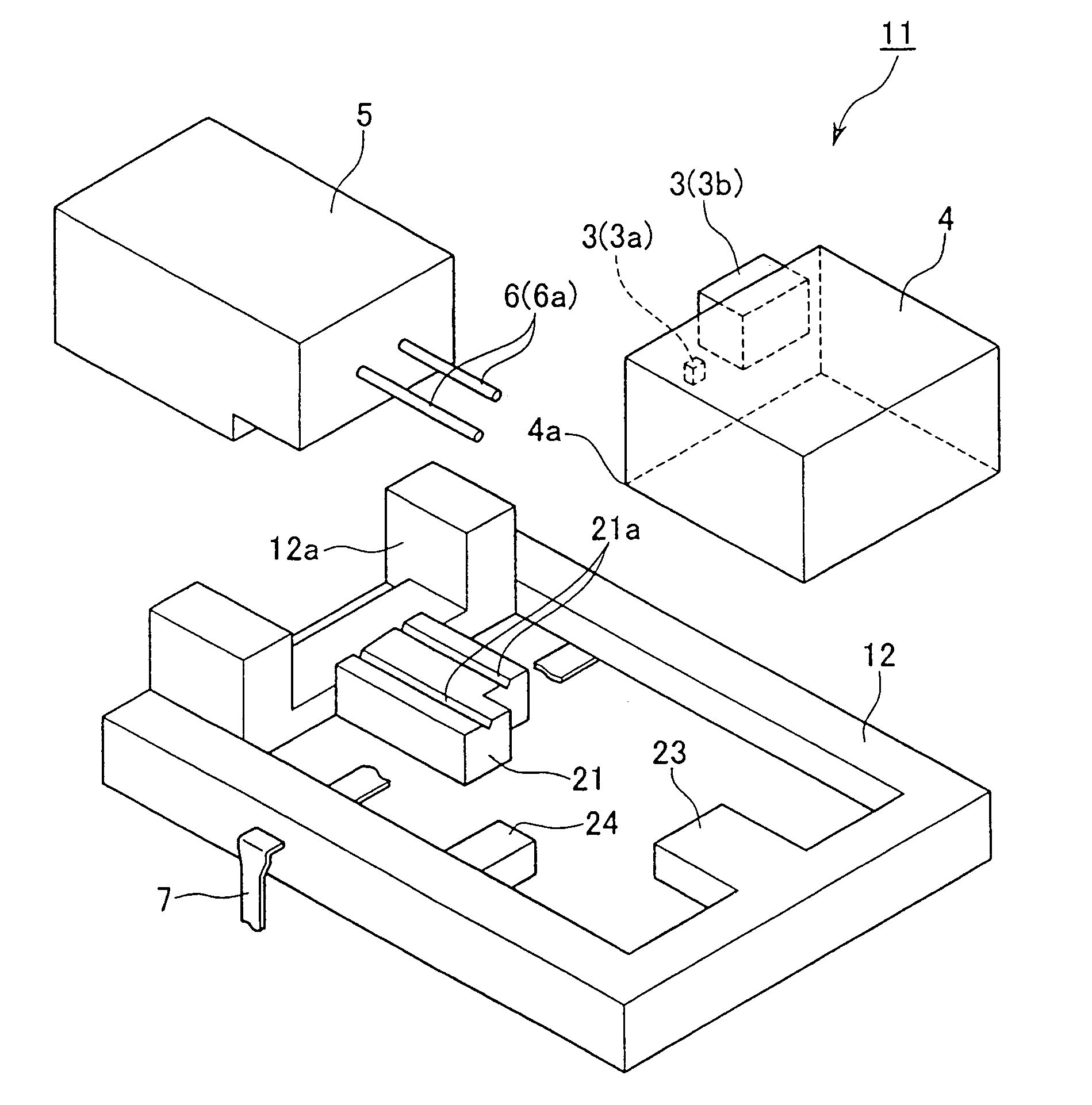
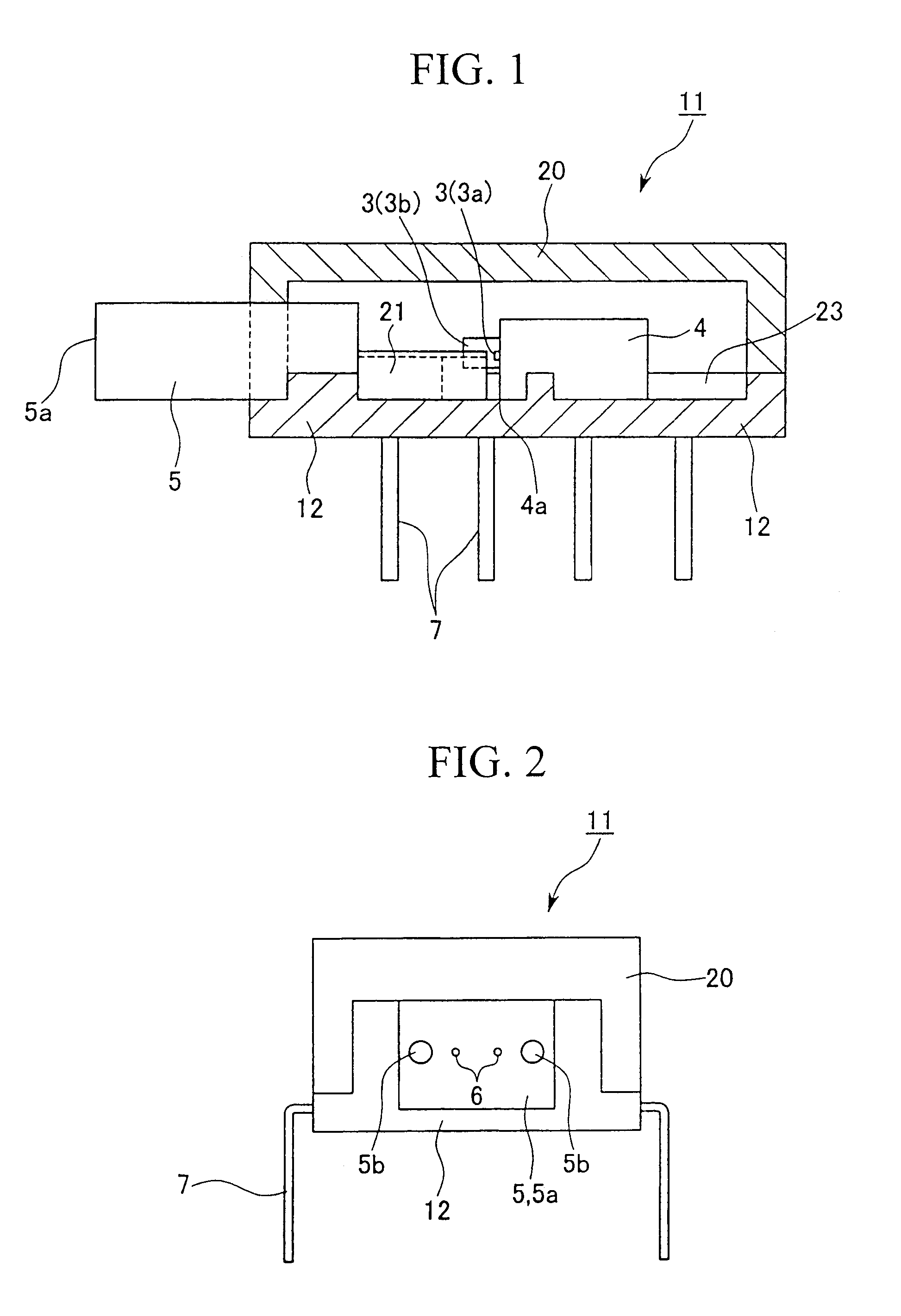
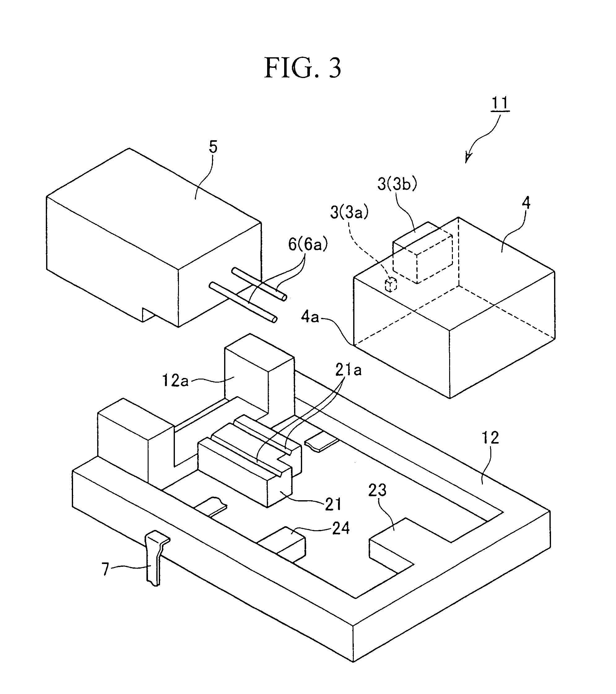
[0061]FIG. 1 is a cross-sectional view of an optical module 11 according to an embodiment of this invention, FIG. 2 is a left-side view of FIG. 1, FIG. 3 is an exploded perspective view of the optical module 11 of FIG. 1 without a cap, and FIG. 4 is a plan view of a package for optical module (hereinafter termed simply “package”) 12 in the optical module 11 of FIG. 1. As shown in these diagrams, the optical module 11 comprises a mount 4 of aluminium die casting and the like, which optical elements such as an LD (in particular, one using a face light-emitting-type semiconductor laser) 3a and a PD (photodiode) 3b are mounted on. The mount 4 is provided in a resin package 12. A ferrule 5 has a constitution resembling a two-filament MT connector, and is attached to the front section of the package 12 as an optical connector section and sealed with a cap 20.

[0062]Said ferrule 5 generally has a box-type outer shape achieve...

second embodiment

[0111]Next, a second embodiment of its will be explained with reference to FIGS. 15 to 18.

[0112]FIG. 15A is a plan view of an optical module 120 according to the second embodiment of this invention, FIG. 15B is a front view, and FIG. 15C is a view from the arrow A of FIG. 15B. FIG. 16 is a perspective view showing the internal structure of the package of the optical module 120 when the mount and the like is removed. FIG. 17 is a cross-sectional view showing a state when a pressing member 125 is provided on a positioning stand 122 of the optical module 120 of FIGS. 15A to 15C, and shows the vicinity of the light-emitting element 3a and the vicinity of the light-receiving element 3b.

[0113]As shown in FIGS. 15A, 15B, 15C, and 16, in this optical module 120, the positioning grooves 123a and 123b on the positioning stand 122 of the package 121, which contains the optical elements 3a and 3b, precisely aligns the position of the optical fibers 124a and 124b with respect to the optical ele...

third embodiment

[0143]Next, a third embodiment of this invention will be explained with reference to FIGS. 20A to 24B.

[0144]FIG. 20A is a plan view of an optical module 30 of this embodiment, FIG. 20B is a front view, and FIG. 20C is a view from the arrow B of FIG. 20B. FIG. 21 is a perspective view of the package internal structure when the mount and the like are removed from the optical module 30. FIG. 22A is a frontal cross-sectional view of the vicinity of optical fiber insertion holes 31 which are provided in the optical module 30 of FIGS. 20A to 20C, FIG. 22B is a cross-sectional view taken along the line C to C of FIG. 22A and shows the vicinity of the optical fiber insertion holes 31 in enlargement, and FIG. 22C is a frontal cross-sectional view of the vicinity of the optical fiber insertion holes 31. Incidentally, the mounts 28a to 28c provided in the package 33 are shown in FIG. 20A, but are omitted from the other diagrams.

[0145]As shown in FIG. 20B, the package 33 is sealed with a cap 20...


PUM


Abstract

A passive method is provided as alignment means for aligning an optical fiber with an optical element in assembling an optical module, while increasing alignment accuracy. A mount (28a) equipped with an optical element (3a) is positioned by abutment on a face (33c) of a projection (33a) formed inside a package (33) and on a side (33g) of a positioning pad (37) projecting from the bottom (33f) of the package. A mount (28b) equipped with an optical element (3b) is positioned by abutment on an inner wall (33b) of the package and on a face (33i) of a projection (33c) formed inside the package. Since the optical power of received or emitted light need not be monitored for fine adjustments of alignment, this method is less expensive.

Description

TECHNICAL BACKGROUND[0001]This invention relates to an optical module, which is an optical-electrical converting component between an optical fiber and an electronic circuit, for example, an optical module mounted in a transceiver and the like for a LAN system such as a G-bit ethernet, an optical element attachment method, and a receptacle-fitted optical module.[0002]An optical module is an optical-electrical converting component wherein optical elements such as an LD (for example, using a face light-emitting-type semiconductor laser) and a PD (photodiode) are mounted on a lead frame, and these are sealed in a resin package (package for optical module). Usually, the optical module is connected to external optical wires by a single-filament or multi-filament optical connector section, attached to the package side face. For example, an SC-type ferrule corresponding to an SC connector is often used as the single-filament optical connector section which is attached to the package side f...

Claims


Application Information

Patent Timeline
Patent Type & Authority Patents(United States)
IPC IPC(8): G02B6/42
CPCG02B6/423G02B6/4201G02B6/421G02B6/4292G02B6/4246G02B6/4249G02B6/4243G02B6/4253G02B6/4255
Inventor ISONO, YOSHIYAWATANABE, TSUTOMUOHSAWA, MAKOTOTANAKA, KOJIIDE, TAKEHISA
Owner THE FUJIKURA CABLE WORKS LTD
Why Eureka
Try Eureka