Image forming apparatus including two developer carrying members wherein potential differences between the developer carrying members and a common voltage source differ
a technology of image forming apparatus and developer carrying member, which is applied in the direction of electrographic process apparatus, instruments, optics, etc., can solve the problems of increasing the size of the electrical circuit board, the cost of the apparatus, and the in-line type image forming apparatus is not always used
- Summary
- Abstract
- Description
- Claims
- Application Information
AI Technical Summary
Benefits of technology
Problems solved by technology
Method used
Image
Examples
embodiment 1
[0039]The present invention is embodied in the form of an in-line type image forming apparatus employing a contact type developing method. This does not mean that the application of this embodiment is limited to an image forming apparatus of the above mentioned type. In other words, the present invention is applicable to any image forming apparatus in accordance with the following description of the preferred embodiments of the present invention, in terms of configuration as well as image formation method.
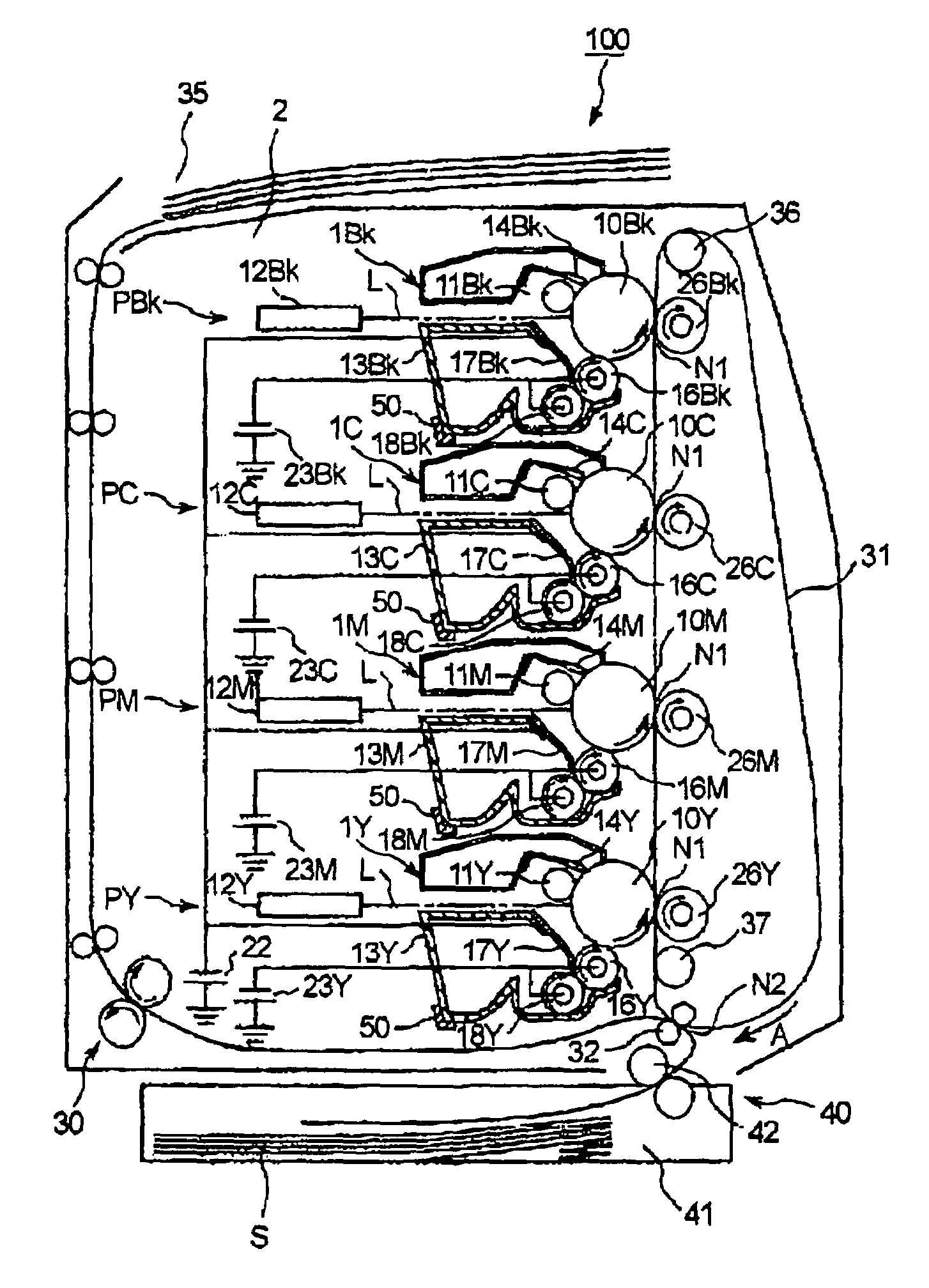
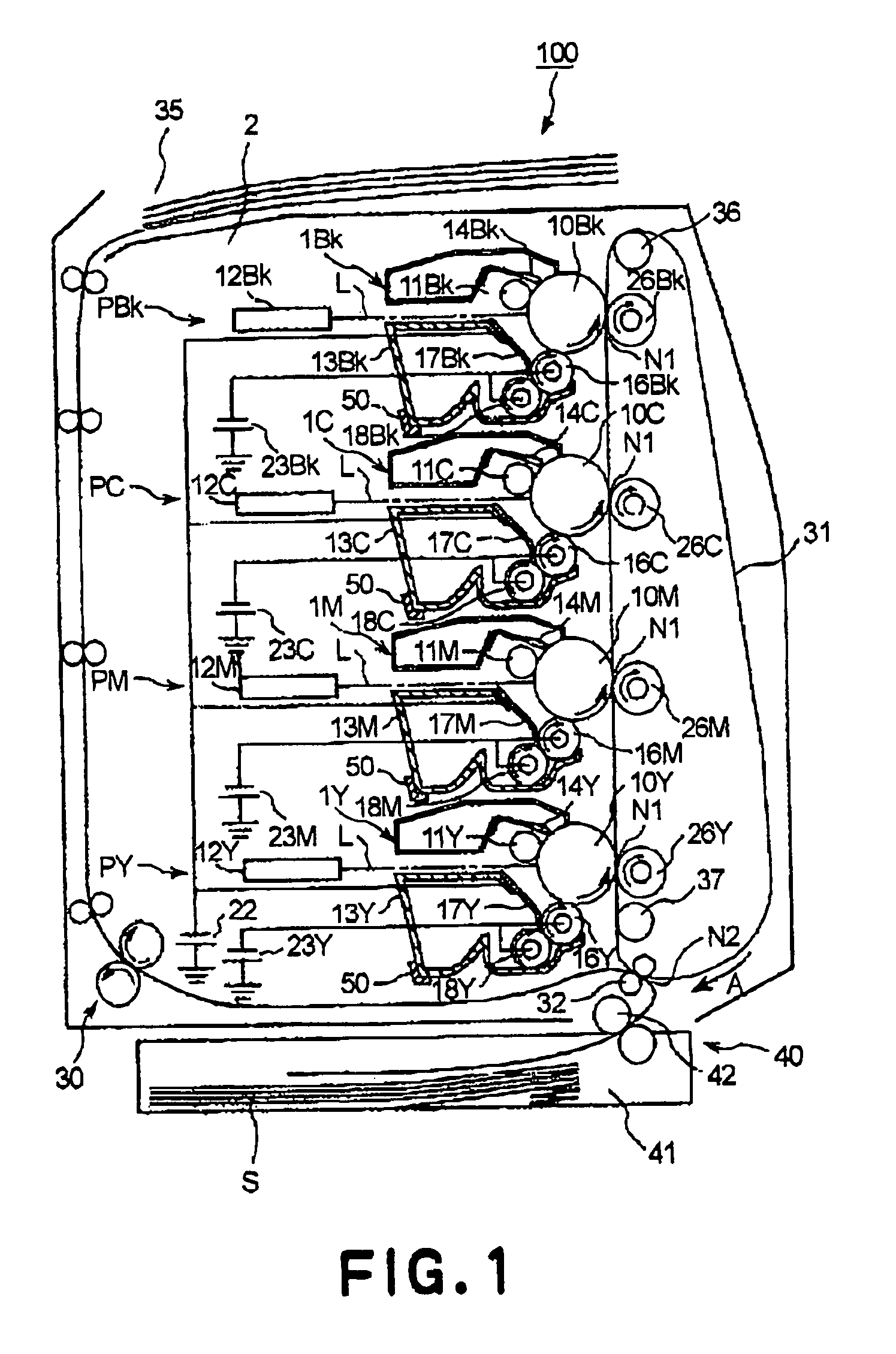
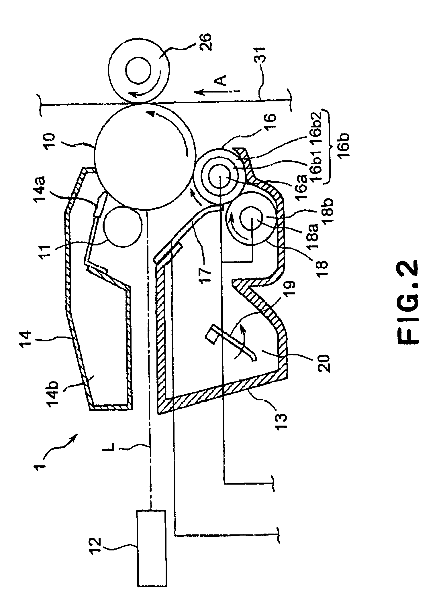
[0040]FIG. 1 is a schematic sectional view of the image forming apparatus 100 in this embodiment of the present invention. The image forming apparatus 100 in this embodiment is an electrophotographic image forming apparatus connected to an external host such as a personal computer. It is capable of outputting an image on a piece of transfer medium, for example, recording paper, OHP sheet, fabric, etc., in response to image formation data signals from the external host.
[0041]The ima...
embodiment 2
[0103]Next, another embodiment of the present invention will be described. The image forming apparatus in this embodiment is identical in base structure and operation. Therefore, the components in this apparatus which are identical in structure and function to those in the first embodiment will be given the same referential symbols as those given in the first embodiment, and will not be descried in detail at this time.
[0104]FIG. 6 is a schematic sectional view of the essential portion, in particular, the portion comprising the photosensitive drums 10, developing apparatuses 13, primary transfer rollers 26, and intermediary transfer belt31, of the image forming apparatus in this embodiment in the monochromatic print mode. As will be evident from the drawing, in the monochromatic print mode, the photosensitive drum 10, development roller 16, toner supply roller 18, and primary transfer roller 26 in each of the yellow, magenta, an cyan image formation stations PY, PM, and PC are kept s...
PUM
 Abstract
Description
Claims
Application Information
 - R&D
- Intellectual Property
- Life Sciences
- Materials
- Tech Scout
- Unparalleled Data Quality
- Higher Quality Content
- 60% Fewer Hallucinations
Browse by: Latest US Patents, China's latest patents, Technical Efficacy Thesaurus, Application Domain, Technology Topic, Popular Technical Reports.
© 2025 PatSnap. All rights reserved.Legal|Privacy policy|Modern Slavery Act Transparency Statement|Sitemap|About US| Contact US: help@patsnap.com


