Method for managing defects of optical disk

a technology of optical disk and defect management, applied in the direction of digital signal error detection/correction, instruments, recording signal processing, etc., can solve the problems of data not being able to be written correctly to defective blocks, data may also be defective, and failure to record data, etc., to achieve the effect of reducing the number of times to write spare packets

Inactive Publication Date: 2006-05-23
MEDIATEK INC
View PDF11 Cites 2 Cited by
  • Summary
  • Abstract
  • Description
  • Claims
  • Application Information

AI Technical Summary

Benefits of technology

[0026]It is therefore a primary objective of the claimed invention to provide a defects management method and associated procedures to make use of memory resources effectively and solve the above-mentioned problem.
[0027]According to the claimed invention, a plurality of buffers is provided in a memory to store temporary packets. The claimed invention can perform defects management on a plurality of defects at the same time so as to release packets of the buffers as soon as possible. During defects management, it takes only a releasable buffer among a plurality of buffers for performing defects management with a fixed number of buffers. For example, if a defect occurs in another spare packet Ps when a spare packet Ps temporarily stored in buffer A is rewritten to an optical disk, the corresponding substitute to the defective spare packet Ps can be released to a buffer B and copy the corresponding data in the buffer A to the spare packet Ps in the buffer B wherein data in the buffer A will be released and the buffer A can become a released buffer. Thus there will still be a releasable buffer left in memory. If other new defective spare data block Bs is detected while a spare packet Ps in a buffer is rewritten, the released buffer A can be used to temporarily store the spare packet Ps for performing defects management. Even if other defective spare data block Bs is detected during rewriting procedure of the spare packet Ps in the buffer B, a fixed number of buffers can satisfy the memory demand on performing defects management. This makes defects management more efficiently and keeps optical drives operating normally. During defects management, each spare packet Ps in a buffer can be used as a cache so that the number of times to write spare packet Ps will be reduced, data access efficacy of the optical drive will be improved, and life span of the optical disk will be prolonged.

Problems solved by technology

However, defects occur when data is written onto an optical disk.
Defects may be caused by many reasons when data is written onto an optical disk such that data will not be able to be written to defective blocks correctly.
Except for a data block Bd, a spare data block Bsin each data area packet DA may also be defective and fail to record data.
It is possible that one normal area on the rewritable optical disk still functions well when data is written onto the area at first, but then the area turns out to be fault when new data is written to that area again.
Since the area functioned well at first, the defect table DT cannot recognize it as a defective one.
It may demand too much to fulfill.
However, in practice, a spare data block Bs in a spare area packet SA might be a defect.
Therefore, the prior art flow 100 cannot make use of memory space of the memory 20 effectively and waste memory resources continuously.
Defects management cannot be done effectively and operation efficiency of the drive 10 will deteriorate.

Method used


Image

  • Method for managing defects of optical disk
  • Method for managing defects of optical disk
  • Method for managing defects of optical disk

Examples


Embodiment Construction

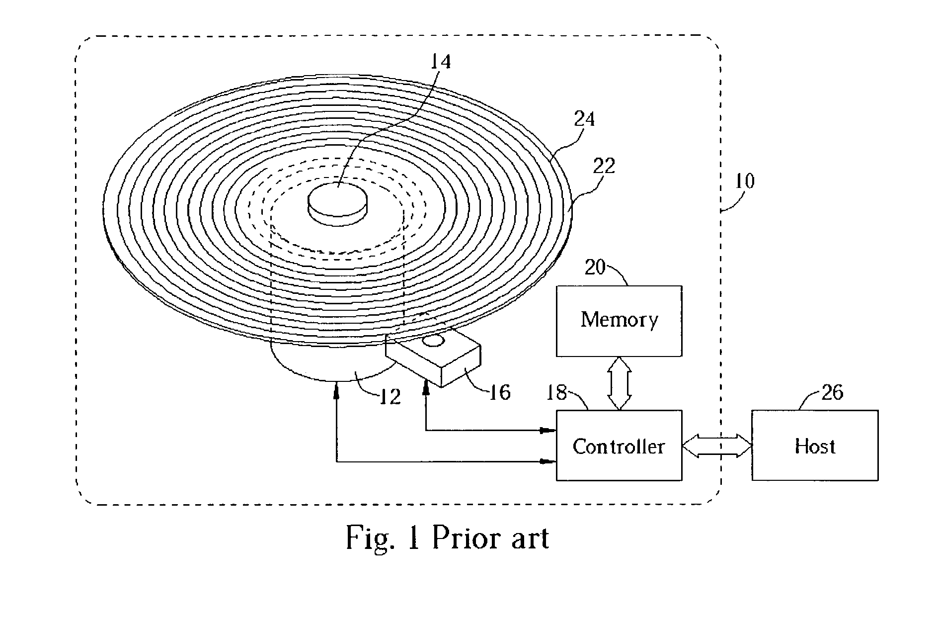
[0038]Please refer to FIG. 6. Illustrated in FIG. 6 is a block diagram of a present invention optical drive 30 for performing defects management. Like the drive 10 illustrated in FIG. 1, a user can access data on an optical disk 22 via a host 46 that controls the drive 30, which can be an optical drive of a personal computer. The drive 30 comprises a motor 32, a pickup head 36, a controller 38, and a memory 40 such as volatile random access memory for storing data during the operation of the controller 38. The motor 32 drives the optical disk 22 to rotate on a shaft 34 so that the controller 38 can access data on the track 24. The controller 38 can control the pickup head 36 to read the data wherein the pickup head 36 skips the track 24 of the optical disk 22 on the housing 34 or transfers the data stored temporarily in the memory 40 to the track 24. A main memory 48 and a plurality of buffers such as buffers 50A and 50B illustrated in FIG. 6 are provided in the present invention op...


PUM

PropertyMeasurementUnit
defectsaaaaaaaaaa
volumeaaaaaaaaaa
flexibilityaaaaaaaaaa

Abstract

A method for accessing data on an optical disk by a drive. The optical disk includes spare packets and data blocks. Each data block is for recording data written to the optical disk, and each spare packet has spare blocks for replacing defect blocks to record data. The drive has a memory allocated with buffers, and each buffer is for recording data of a spare packet. When writing data of a first buffer to a packet of the optical disk, if a plurality of first spare blocks are found defective, then searching a second spare packet which has spare blocks for replacing the first blocks. If the second spare packet is not read in a buffer, reading the second spare packet into a releasable buffer. After copying data written to the first spare blocks from the first buffer to the second buffer, making the first buffer releasable.

Description

BACKGROUND OF INVENTION[0001]1. Field of the Invention[0002]The present invention relates to a method to manage defects of an optical disk. More specifically, a method sets up a plurality of buffers in memory of an optical drive to improve memory use efficiency and defect regulation during optical disk defect management.[0003]2. Description of the Prior Art[0004]Optical disks, due to their small volume and large storage capacity, have become one of the most common volatile data storage media used in modern society. More specifically, development of rewritable optical disks being capable of recording personal data according to a user has largely expanded the flexibility of the use of optical disk. However, defects occur when data is written onto an optical disk. Managing defective areas on an optical disk to maintain the function of recording data concisely has become a focus of the industry.[0005]A drive is required to accesses data in a corresponding optical disk. Please refer to F...

Claims


Application Information

Patent Timeline
Patent Type & Authority Patents(United States)
IPC IPC(8): G06F11/16G11B20/10G11B20/18
CPCG11B20/10527G11B20/1883G11B2220/20G11B2020/1062
Inventor WU, TSE-HONGWU, YUAN-TINGLEE, MING-HUNG
Owner MEDIATEK INC
Why Eureka
Try Eureka