
Seamed, conformable belt and method of making

a technology of conformable belts and seamed, which is applied in the field of seamed, conformable belts and a method of making seamed, and conformable belts, can solve the problems of not being able to meet the requirements of many more sophisticated applications of belt technology in common practice today, the manufacturing process of seamless belts is rather complicated and expensive, and the manufacturing process of seamless belts is approximately 5–10 times more expensive than seamed belt fabrication. , to achieve the effect of eliminating the “bump

Inactive Publication Date: 2006-05-30
XEROX CORP
View PDF65 Cites 35 Cited by
  • Summary
  • Abstract
  • Description
  • Claims
  • Application Information

AI Technical Summary

Benefits of technology

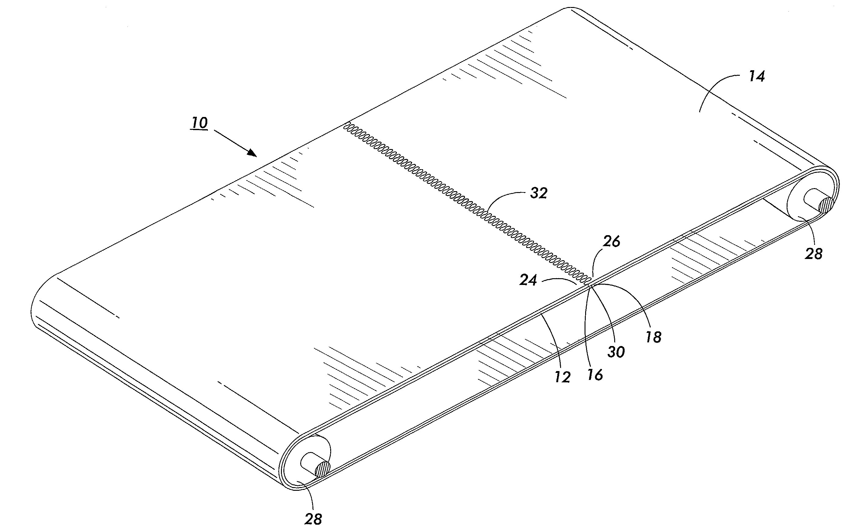
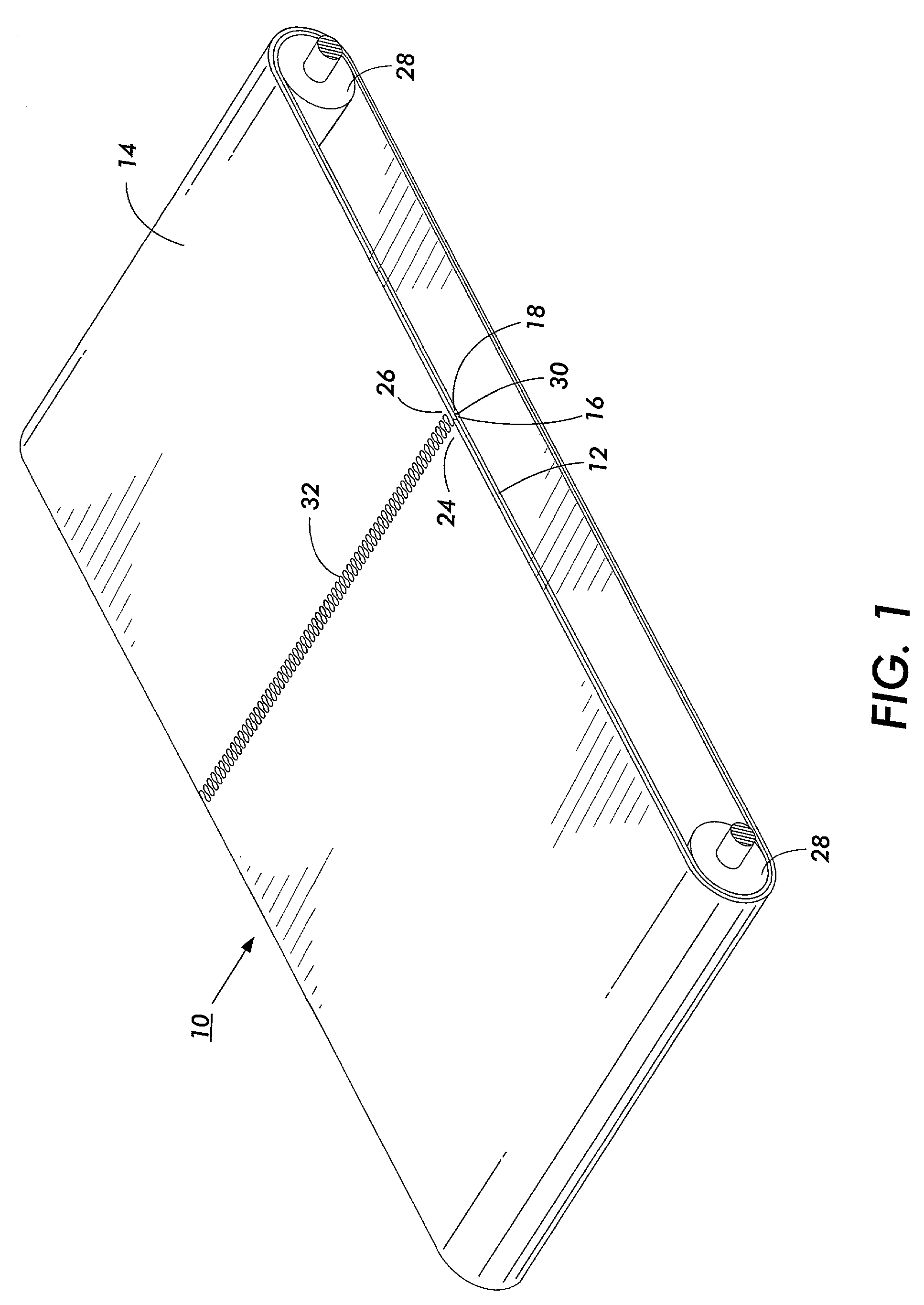
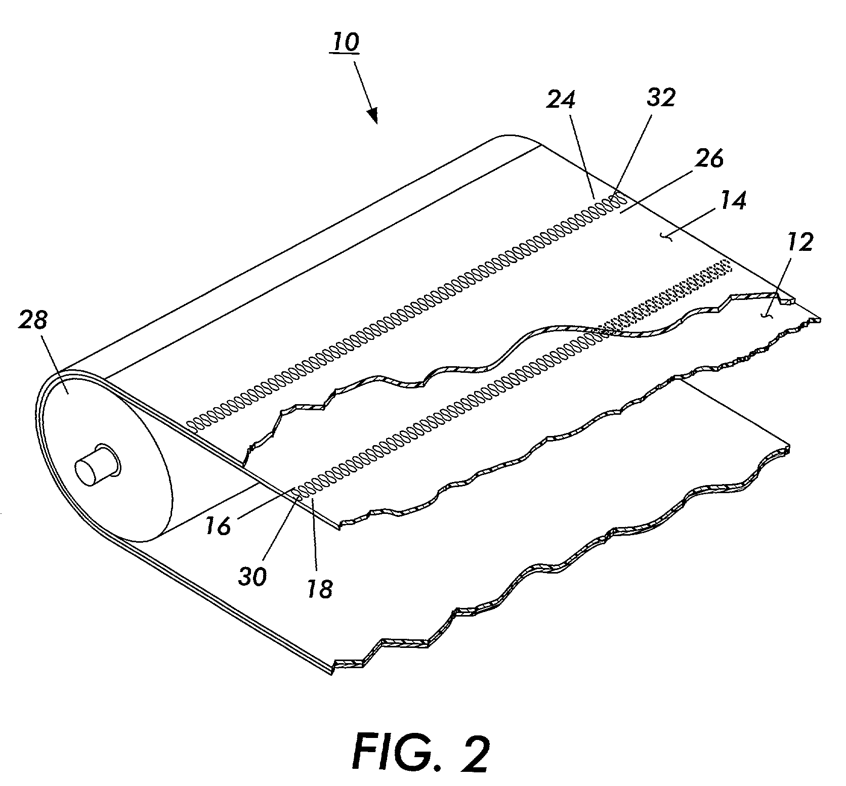
[0015]A seamed, conformable belt in accordance with the present invention includes an elastomeric layer with a substantially planar seam, which eliminates the “bump” produced by typical seamed belts that can interfere with the electrical and mechanical operations of the belt. In addition, in embodiments of the present invention, the ends of the elastomeric layer (and, optionally, the substrate) of the belt of the present invention are not bonded together (i.e., are detachable). Thick conformable material can be die or laser cut to geometries that mechanically lock the ends together when mating. This also can allow the adjacent ends of the elastomeric layer to mold into each other when subjected to heat and / or pressure, thereby forming a tight, planar seam in the elastomeric layer. In addition, the lack of bonding between the ends of the elastomeric layer enables the elastomeric layer of the belt to be easily replaced, without the need for replacing the substrate. Further, the lack of bonding between the ends of the elastomeric layer eliminates the need for selecting a bonding agent, e.g., an adhesive, of appropriate conformability and modulus of elasticity to join together the ends of the elastomeric layer.
[0016]The belts of the present invention are useful to generate a nip width, to deliver heat for fusing / transfix, or to provide the right coefficient of friction. In addition, the belts of the present invention may also be candidates for paper handling belts and for imaging purposes, e.g., as intermediate transfer belts, by providing a top coating or special treatment for the belts.

Problems solved by technology

While such joined or seamed belts are suitable for many applications, such as the delivery of rotary motion from a source such as a motor, to implement a device such as a saw blade, they are not as satisfactory in many of the more sophisticated applications of belt technology in common practice today.
While this is ideal, the manufacture of seamless belts requires rather sophisticated manufacturing processes which are expensive.
Typically, seamless belt fabrication is approximately 5–10 times more expensive than seamed belt fabrication.
Larger belts are also very difficult to handle in the seamless belt fabrication process.
This leads to a significant height differential over the adjacent portions of the belt, of at least 0.003 inches or more depending on the belt thickness, which leads to performance failure in many applications.
In an electrostatographic imaging process utilizing an overlapping ultrasonically welded seamed belt, two severe problems that are encountered during the imaging and cleaning processes are cleaning the imaging belt of residual toner after transfer of the toner image due to the excess in seam height and dynamic fatigue seam cracking as a result of large induced bending stress caused by the increase in seam thickness.
In particular, with a bump, crack, or other discontinuity in the seam area of the belt, the cleaning function of a blade is affected which allows toner to pass under the blade and not be effectively cleaned off from the imaging belt surface.
A crack in the seam may also become a site that collects and traps toners which are eventually spewed out to the imaging zones of the imaging belt surface causing copy printout defects.
Furthermore, seams having differential heights may, when subjected to repeated striking by cleaning blades, cause the untransferred, residual toner to be trapped in the irregular surface morphology of the seam.
Since the severe mechanical interaction between the cleaning blade and the seam also causes blade wear problems, the result often observed is that both the cleaning life of the blade and the overall life of the imaging belt under a service environment can be greatly diminished as well as degrading the copy print-out quality.
In addition, the mechanical striking of the cleaning blade over the excessive seam height has also been found to give rise to vibrational disturbance in the imaging development zone which affects the toner image formation on the belt and degrades resolution and transfer of the toner image to a receiving copy sheet.
Moreover, the discontinuity or seam bump in such a belt may result in inaccurate image registration during development, inaccurate belt tracking, and overall deterioration of motion quality, as a result of the translating vibrations.
However, such interlocking seams require careful control of the properties of the adhesive used to bond together the seam ends and careful control of the thickness of the bonded seam.

Method used


Image

  • Seamed, conformable belt and method of making
  • Seamed, conformable belt and method of making
  • Seamed, conformable belt and method of making

Examples


second embodiment

[0047]While FIGS. 1–3 illustrate a two layer belt, the principles of the present invention can be used with belts having more layers. For example, additional elastomeric layers can be coated sequentially onto the first surface 20 of the substrate. Alternatively, in the present invention, additional elastomeric layers can be coated onto the second surface 22 of the substrate, as shown in FIG. 8. In this embodiment, the belt 10 further includes a lower elastomeric layer 44, which like elastomeric layer 14 will maintain its strength and other properties with repeated cycling under the desired conditions of use (e.g., high temperature).

[0048]The seamed, conformable belt 10 in accordance with the present invention may further include a reinforcement members on either or both sides of the belt. Suitable reinforcement members are known in the art and include tape and beads of elastomers.

third embodiment

[0049]Referring to FIGS. 9 and 10, a seamed, conformable belt in accordance with the present invention is shown. In this embodiment, the seamed conformable belt 10 is identical to the above-described seamed, conformable belt, except the first end 24 and the second end 26 of the elastomeric layer 14 are bonded together to form a second, bonded interlocking seam 32′.

[0050]As shown in FIG. 9, the first end 24 and the second end 26 may be bonded as described above, for example, using an adhesive which is compatible with the elastomeric layer and which exhibits similar properties to the elastomeric layer. In yet another embodiment, as shown in FIG. 9, a separate topcoat 48 for imaging purposes may be provided.

[0051]Alternatively, as shown in FIG. 10, the first end 24 and the second end 26 may be bonded through the use of a topcoat material 46 which may comprise an adhesive. The topcoats 46 and 48 may be applied using conventional processes, such as dip coating, flow coating, and spray co...


PUM

PropertyMeasurementUnit
Thicknessaaaaaaaaaa
Thicknessaaaaaaaaaa
Thicknessaaaaaaaaaa

Abstract

A seamed, conformable belt including a substrate having first and second opposing substantially planar surfaces, a first end, and a second end, wherein the first end and the second end of the substrate form a first seam, and an elastomeric layer having a first end and a second end, wherein the elastomeric layer is adjacent and in contact with the first surface of the substrate and wherein the first end and the second end of the elastomeric layer form a second detachable, substantially planar seam.

Description

CROSS REFERENCE TO RELATED APPLICATIONS[0001]The following applications are related to the present application: U.S. patent application Ser. No. 09 / 493,445, filed Jan. 28, 2000, entitled, “Process and Apparatus for Producing an Endless Seamed Belt;” U.S. patent application Ser. No. 09 / 470,931, filed Dec. 22, 1999, entitled, “Continuous Process for Manufacturing Imageable Seamed Belts for Printers;” U.S. patent application Ser. No. 09 / 088,011, filed May 28, 1998, entitled, “Unsaturated Carbonate Adhesives for Component Seams;” U.S. patent application Ser. No. 09 / 615,444, filed Jul. 13, 2000, entitled, “Polyimide Adhesive For Polyimide Component Interlocking Seams;” U.S. patent application Ser. No. 09 / 615,426, filed Jul. 13, 2000, entitled, “Process For Seaming Interlocking Seams Of Polyimide Component Using Polyimide Adhesive;” U.S. patent application Ser. No. 09 / 660,248, filed Sep. 13, 2000, entitled, “Imageable Seamed Belts Having Fluoropolymer Adhesive Between Interlocking Seaming...

Claims


Application Information

Patent Timeline
IPC IPC(8): F16G3/00F16G7/04B29D29/00B29K21/00F16G3/10G03G15/00G03G15/16
CPCB29C65/56B29C66/2272B29C66/4322B29C66/4324B29C66/723F16G3/00F16G3/10G03G15/754G03G15/162B29C65/48B29C66/1142Y10T428/192G03G2215/1695B29C66/729B29C66/7294B29C65/4815B29C65/4845B29C66/71B29L2031/709B29K2023/00B29K2023/06B29K2023/12B29K2027/06B29K2033/08B29K2033/12B29K2067/00B29K2069/00B29K2075/00B29K2077/00B29K2079/08
Inventor BATTAT, DAVIDSCHLUETER, JR., EDWARD L.
Owner XEROX CORP
Learn More