Method and apparatus for cooling a contacting surface of an ultrasound probe

a technology of ultrasound probes and contacting surfaces, which is applied in the field of imaging probes, can solve the problems of fixed thermal conduction of diamond films, limited acoustic output, and inability to thermally couple with biological tissues,

Inactive Publication Date: 2006-05-30
KONINKLIJKE PHILIPS ELECTRONICS NV
View PDF18 Cites 83 Cited by
  • Summary
  • Abstract
  • Description
  • Claims
  • Application Information

AI Technical Summary

Benefits of technology

[0008]Preferably, the cooling medium further includes circulation apparatus for enabling circulation of the circulating cooling fluid within the conduit, and a control system having a sens...

Problems solved by technology

Prescribed limits are set or prescribed by governing agencies as to the amount of heat that can be allowed to build up on the surface of the probe, typically limiting the surface temperature of the probe tip to a predetermined temperature or to a predetermined increase above ambient temperature, and hence limiting the acoustic output.
However, the diamond film must be ext...

Method used


Image

  • Method and apparatus for cooling a contacting surface of an ultrasound probe
  • Method and apparatus for cooling a contacting surface of an ultrasound probe
  • Method and apparatus for cooling a contacting surface of an ultrasound probe

Examples


first embodiment

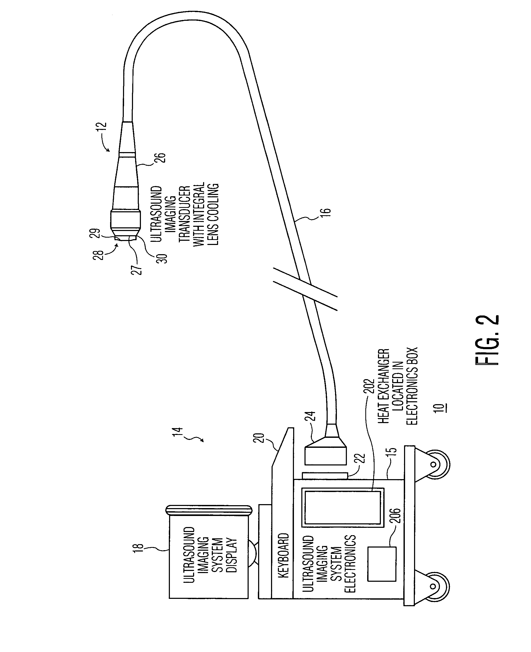
[0021]FIG. 2 shows the present invention in which the cooling conduit system 28 further includes a heat exchanger 202 housed in console 14, and conduits extending through cable 16. A cooling medium passes through the cooling conduit system 28 over the tip 30 of the probe 12 for transferring heat from the tip 30 of the probe 12, away from the tip 30 of the probe 12, through the conduits extending through cable 16, and to the heat exchanger 202. At the heat exchanger 202, a heat sink is provided for removing heat from the cooling medium. The cooled cooling medium then flows through the conduits in cable 16 to the tip 30 of the probe 12.

[0022]The heat exchanger 202 uses heat removal methods that are known to one skilled in the art, such as thermoelectric cooling, evaporative cooling, circulation, etc. Circulation may be passive or active. Active circulation is implemented using conventional circulating means, such as a pump, fan or suction means employing negative pressures, included i...

second embodiment

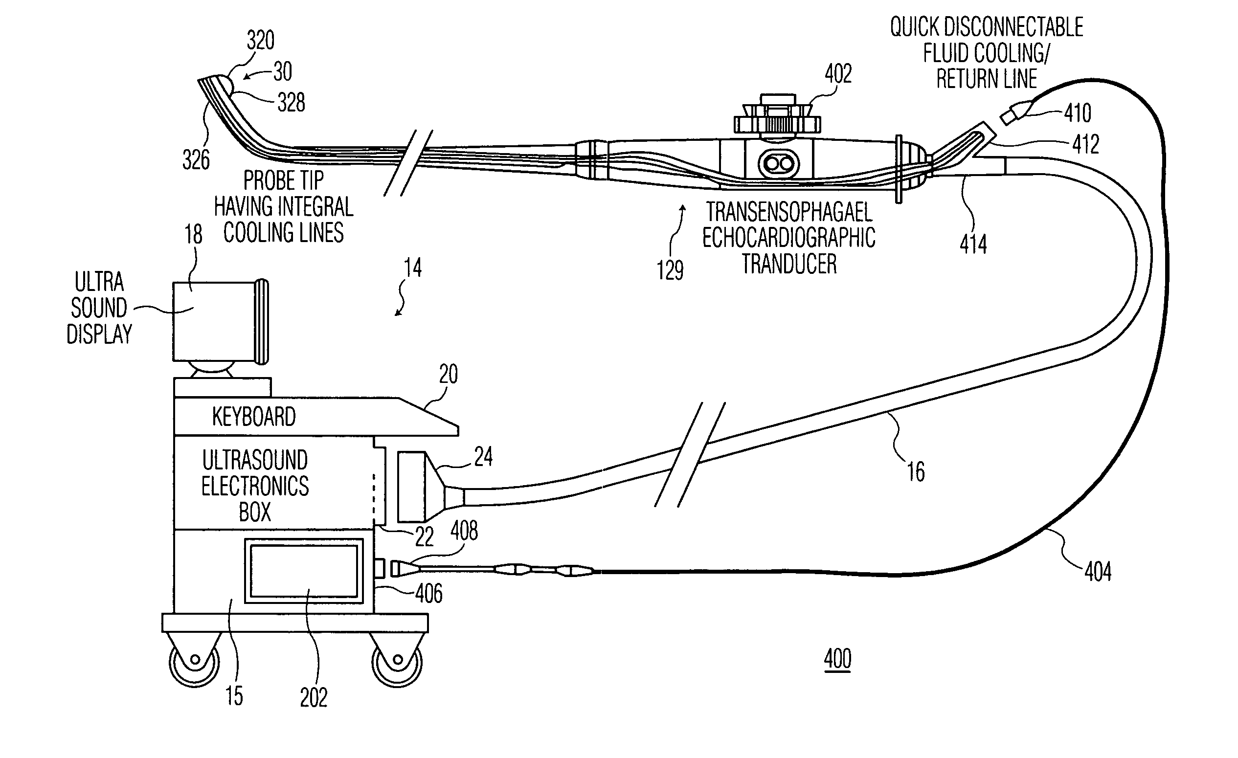
[0032]With reference to FIG. 4, ultrasound imaging system 400 is shown, illustrating the invention. The probe shown is a Trans-Esophageal Echocardiographic (TEE) probe. However, other types of probes may be substituted. The TEE probe includes an elongated distal end portion and probe tip articulation controls 402. The inlet cooling line 326 and outlet cooling line 328 extend from the tip 30 to the proximate end of the probe 12A. A fluid connector line 404 is provided for providing respective paths between the inlet and outlet cooling lines 326, 328 and the console 14. Cable 16 is a conventional cable for housing the ultrasound cable 313 having connectors 22, 24 for transferring signals between the console 14 and the probe 12A.

[0033]The fluid connector line 404 and heat exchanger 202 are provided with mating connectors 406 and 408, respectively, for allowing exchange of the cooling medium between the fluid connector line 404 and the heat exchanger 202. The fluid connector line 404 an...

third embodiment

[0034]With reference to FIG. 5, a cooling conduit system 500 for a probe 12B of an ultrasonic imaging system is shown in a Conduit cooling system 500 includes a conduit 502 through which the cooling medium flows and heat exchanger 503 for providing a heat sink for the flowing cooling medium. The conduit passes over the outer surface of the tip 30 of probe 12B. The portion of the conduit 502 positioned directly above acoustic lens, or other structure located at the outer surface of the tip 30, through which the acoustic energy is transmitted and received forms a window 504.

[0035]The conduit 502 is formed of a single tube shaped membrane coupled or bonded to existing materials within the probe 12B, and the cooling medium flows through a conduit formed within the tube. Top and bottom surfaces 506, 508, respectively, of the window 504 are formed of the portion of the tube shaped membrane located directly above an acoustic lens 510, or in the absence of a lens, directly above the final ...


PUM


Abstract

A cooling system for an ultrasonic imaging system is provided, the ultrasonic imaging system having a probe for transmitting and receiving acoustic signals through a tip of the probe to and from biological tissue contacting the tip at an outer surface of the tip. The cooling system includes a conduit for circulating cooling medium therein, and a heat exchanger in fluid communication with the circulating cooling medium and having means for removing heat from the circulating cooling medium, wherein at least a portion the conduit is in proximity to or contacts the outer surface of the probe tip. In a first embodiment the conduit includes an inlet fluid line extending from the heat exchanger to the tip of the probe for providing the circulating cooling medium from the heat exchanger to the probe tip, and an outlet cooling line extending from the tip of the probe to the heat exchanger for providing circulating cooling medium from the probe tip to the heat exchanger. In a second embodiment the heat exchanger is housed in the probe. In a third embodiment, the probe is housed within a housing, wherein a portion of the conduit extends from the tip of the probe along an external surface of the housing.

Description

FIELD OF THE INVENTION[0001]The present invention generally relates to imaging probes, and in particular to a system and method for cooling a tip of the imaging probes.BACKGROUND OF THE INVENTION[0002]Ultrasound diagnostic technology generally relates to imaging of biological tissue using an ultrasonic transducer probe. The probe includes a transducer which transmits ultrasonic waves and receives ultrasonic echoes reflected from the tissue. The transducer is typically placed on the body surface or internal to a body lumen of a patient in a selected imaging region. The ultrasound transducer generates and directs ultrasonic waves to the imaging region. The transducer then receives ultrasonic waves reflected from the region and converts the received waves into electrical signals that are processed to form a diagnostic image.[0003]A thermal build-up is created in the probe during transmission due to acoustic losses being converted into heat. Prescribed limits are set or prescribed by go...

Claims


Application Information

Patent Timeline
IPC IPC(8): A61B8/00A61B8/12H04R1/02
CPCA61B8/445A61B8/546A61B8/4281A61B8/12
Inventor PESZYNSKI, MICHAELMERLO, JOHN J.RIELLY, MATTHEW ROBERT
Owner KONINKLIJKE PHILIPS ELECTRONICS NV
Why Eureka
Try Eureka