
Multi-pair aggregate power distribution

a power distribution and aggregate technology, applied in the field of electric power distribution, can solve the problems of not providing an efficient or even feasible means for transmitting power to a remote device, dsl-like devices are not within the scope of the 802.3af standard, and not being able to extend the advantag

Active Publication Date: 2006-05-30
CISCO TECH INC
View PDF9 Cites 80 Cited by
  • Summary
  • Abstract
  • Description
  • Claims
  • Application Information

AI Technical Summary

Benefits of technology

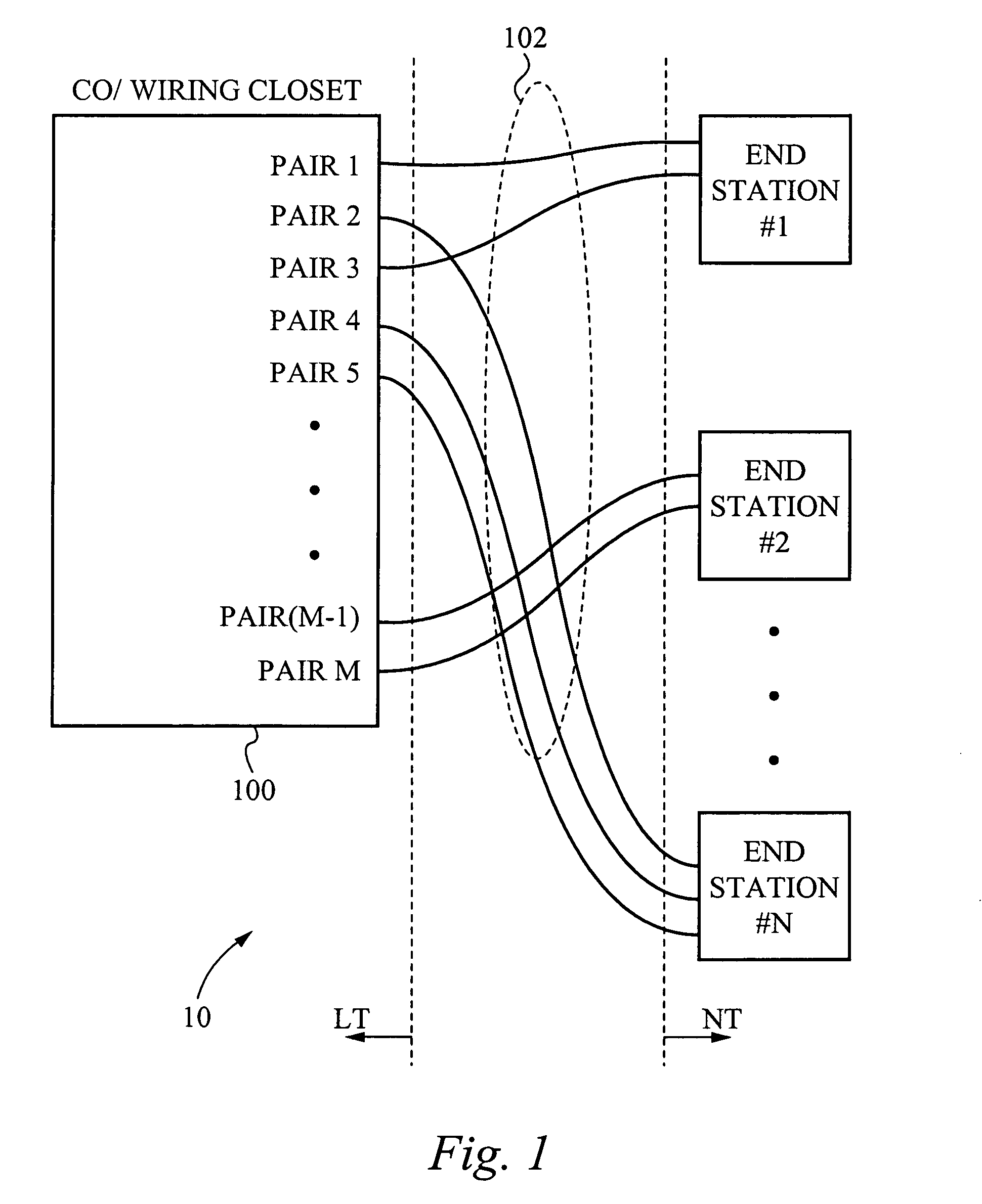
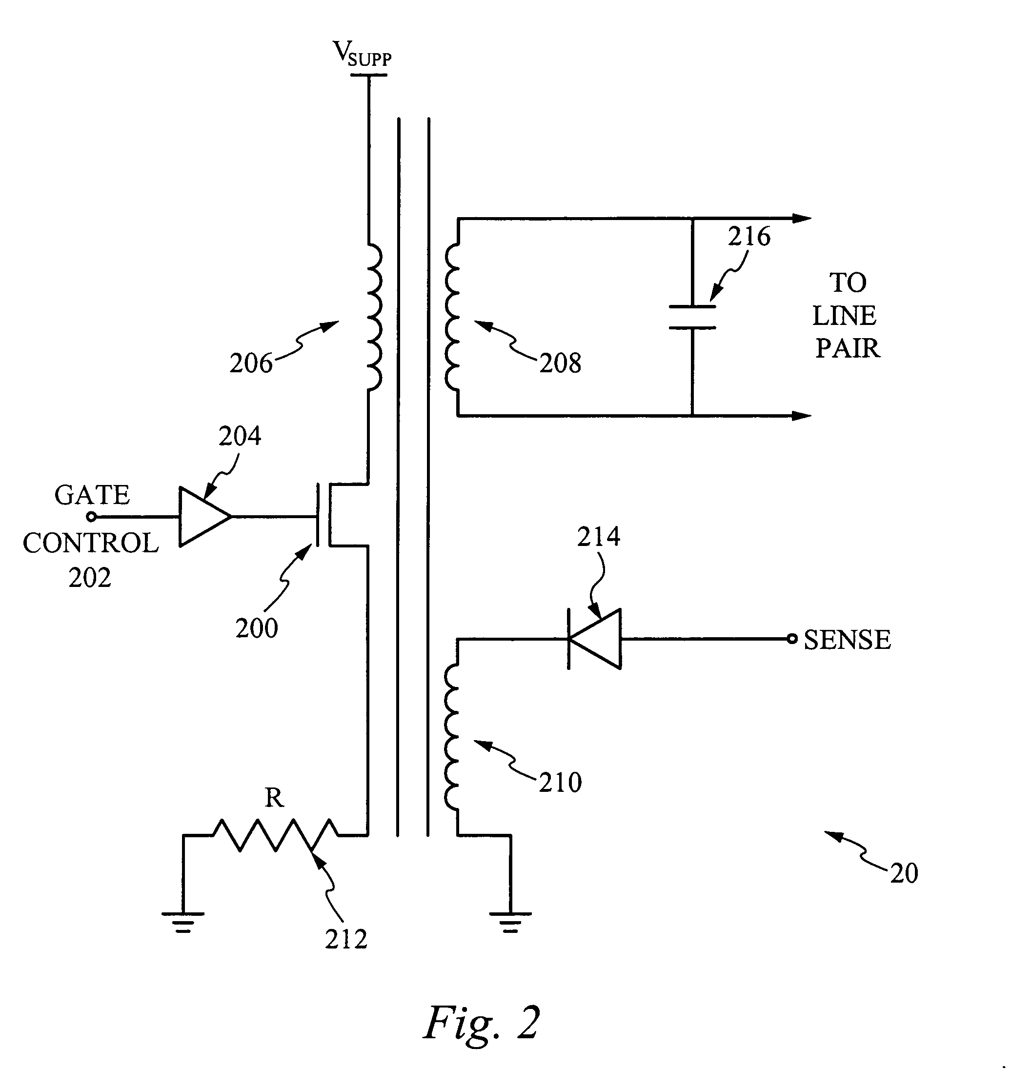
[0010]According to yet another aspect of the present invention, a method of providing power to an electronic device comprises coupling an electronic device to first and second conducting pairs, said first and second conducting pairs being non-adjacent conducting pairs provided by a wiring closet or central office, applying power to the first and second conducting pairs, limiting a current drawn through the first and second conducting pairs to a predetermined limited current, sensing the predetermined limited current drawn by the electronic device, determining a current demand of the electronic device, based on the predetermined limited current drawn by the electronic device, and permitting the current demand of the electronic device to increase to a full demand, so long as the current demand does not exceed a maximum current carrying limit of the first and second conducting pairs.

Problems solved by technology

However, due to the relatively larger power demands of such devices, regulatory limits on the power that may be transmitted over PSTN twisted pair cabling, and the high resistance of PSTN twisted pairs (which can be up to 1300 Ω or 250 Ω / km for a given pair), solutions to extend the advantage have not been feasible.
Because of the problems of transmitting power over the PSTN (public switched telephone network), and to the PSTN, e.g., private branch exchange (PBXs), however, DSL (digital subscriber line) and DSL-like devices are not within the scope of the 802.3af standard.
A principle reason for this is that traditional DSL operates over the PSTN and at long distances and, therefore, does not provide an efficient or even feasible means for transmitting power to a remote device.
DSL devices typically require more power than a PSTN conducting pair is capable of carrying or is permitted to carry due to regulatory concerns.
Indeed, in most instances the PSTN pair used for traditional DSL is not even able to carry the current that would be necessary to power the DSL interface of a DSL device, not to mention the current that would be required to power the remaining technology making up the DSL device.
Unfortunately, however, the distances are still too great for most applications, particularly at the maximum reach of VDSL.
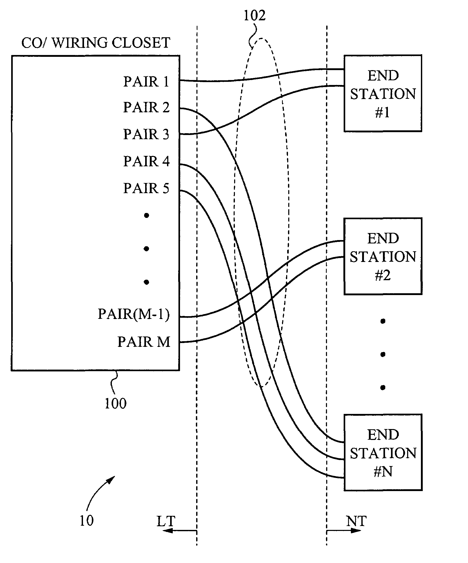
However this approach is not practicable since adjacent pairs of a DSL system from the wiring closet or CO, i.e., from the line termination (LT) of the system, are arbitrarily routed so that there is no guarantee that they maintain their adjacency at the network termination (NT) of the system.

Method used


Image

  • Multi-pair aggregate power distribution
  • Multi-pair aggregate power distribution
  • Multi-pair aggregate power distribution

Examples


Embodiment Construction

[0020]Those of ordinary skill in the art will realize that the following detailed description of the present invention is illustrative only and is not intended to be in any way limiting. Other embodiments of the present invention will readily suggest themselves to such skilled persons having the benefit of this disclosure.

[0021]Embodiments of the present invention are described herein in the context of methods of and apparatuses for using multiple conducting pairs to transmit power to remote electronic devices. While not expressly shown in the drawings, one skilled in the art will understand that the conducting pairs over which power is transmitted to the various remote devices may also be used to for communicating data and voice information to / from the remote devices. Reference will now be made in detail to implementations of the present invention as illustrated in the accompanying drawings. The same reference indicators will be used throughout the drawings and the following detail...


PUM


Abstract

Apparatus and methods for transmitting power over non-adjacent multiple conducting pairs and aggregating power from the conducting pairs to power a remote electronic device. In an embodiment, the apparatus and method comprises a wiring closet which has power supplying capabilities for providing power to a plurality of conducting pairs. A remote termination is adapted to aggregate power provided to and transmitted by two or more non-adjacent conducting pairs. The aggregated power is supplied to a remote electronic device. Preferably, a plurality of power circuits provide power to the conducting pairs. Preferably one or more rectifier circuits aggregate power from the non-adjacent pairs to the remote electronic device.

Description

FIELD OF THE INVENTION[0001]The present invention relates generally to electrical power distribution. More particularly, the present invention relates to methods of and apparatuses for transmitting and aggregating power over multiple conducting pairs to remote devices.BACKGROUND OF THE INVENTION[0002]For many years conventional telephone handsets have been powered from a central office (CO) or a wiring closet of a private branch exchange (PBX). Power from the CO is supplied over the same twisted pair as is used for voice communication between the CO and the handset. In other words, the power distribution and voice communication medium comprises a single twisted pair within the PSTN (public switched telephone network). Because conventional telephone handsets are powered independent of the electrical power grid, they are able to continue functioning even when power on the electrical power grid is disrupted, for example as may happen due to a power outage.[0003]It would be desirable to...

Claims


Application Information

Patent Timeline
IPC IPC(8): H01B11/02H02B1/20H02J3/00H02M1/10
CPCH02J1/10H04Q2213/1308
Inventor BARRASS, HUGH
Owner CISCO TECH INC
Learn More