
LCD with power conversion capability

a technology of power conversion capability and lcd, applied in the field of lcd, can solve the problems of limited operating space, manufacturer's failure to repair the converter, and inconvenient, and achieve the effect of reducing electromagnetic interferen

Inactive Publication Date: 2006-05-30
WISTRON CORP
View PDF10 Cites 2 Cited by
  • Summary
  • Abstract
  • Description
  • Claims
  • Application Information

AI Technical Summary

Benefits of technology

[0008]Accordingly, an object of the invention is to provide an LCD with power conversion capability that can work normally without an external power converter and thus conserve operating space.
[0009]Another object of the invention is to provide an LCD with power conversion capability that implements power conversion inside the LCD to eliminate the need for providing different DC outputs and simplify the power circuit design, thereby reducing the required cost.
[0011]A further object of the invention is to provide an LCD with power conversion capability that provides effective protection for the power circuit in the LCD to reduce the failure rate and offer better power quality for the LCD in use.
[0013]The linear filter unit can reduce electromagnetic interference (EMI). The rectification / filter unit coupled to the linear filter unit can convert the AC input into a ripple DC voltage. The power conversion unit coupled to the rectification / filter unit can convert the ripple DC voltage into DC voltage. The output rectification / filter unit coupled to the power conversion unit can filter the DC voltage and output a desired DC voltage. The driving unit coupled to the power conversion unit can control the power conversion unit for power conversion. The feedback unit coupled to the output rectification / filter unit can sense the desired DC voltage variation. The power management unit coupled with the rectification / filter unit, the power conversion unit, the driving unit and the feedback unit can receive a start voltage from the rectification / filter unit to output a series of impulses for the driving unit and adjust the impulse width of the series based on the variation of the desired DC voltage sensed by the feedback unit.

Problems solved by technology

However, the converter 2a is implemented outside the LCD 1a. This limits operating space.
However, in fact, the LCD manufacturer does not repair the converter 2a but transports the converter 2a to and from its manufacturer.
This is not convenient and takes time.

Method used


Image

  • LCD with power conversion capability
  • LCD with power conversion capability
  • LCD with power conversion capability

Examples


Embodiment Construction

[0018]The following numbers denote the same elements throughout the description and drawings.

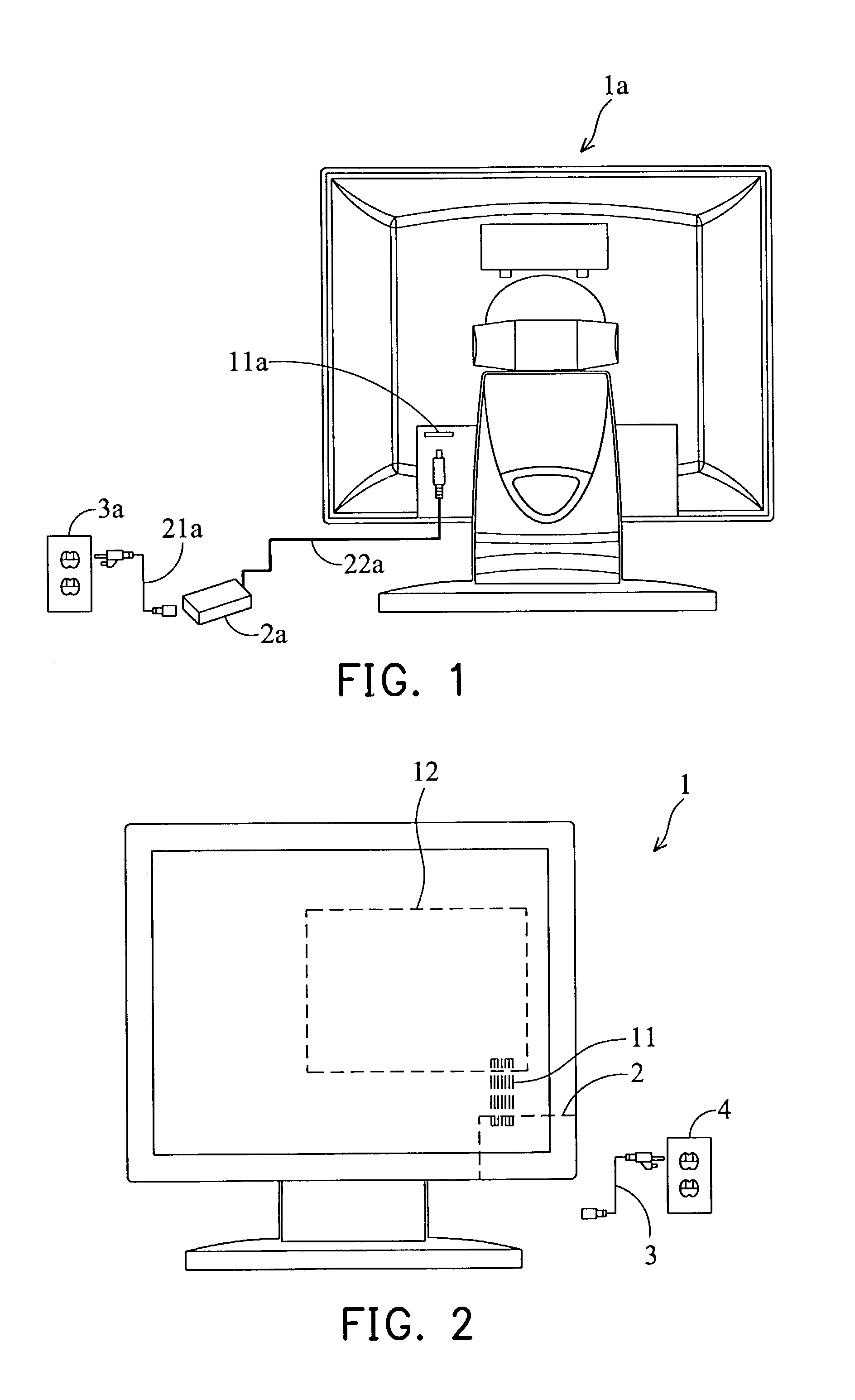
[0019]FIG. 2 is a schematic elevation diagram of a first embodiment according to the invention. As shown in

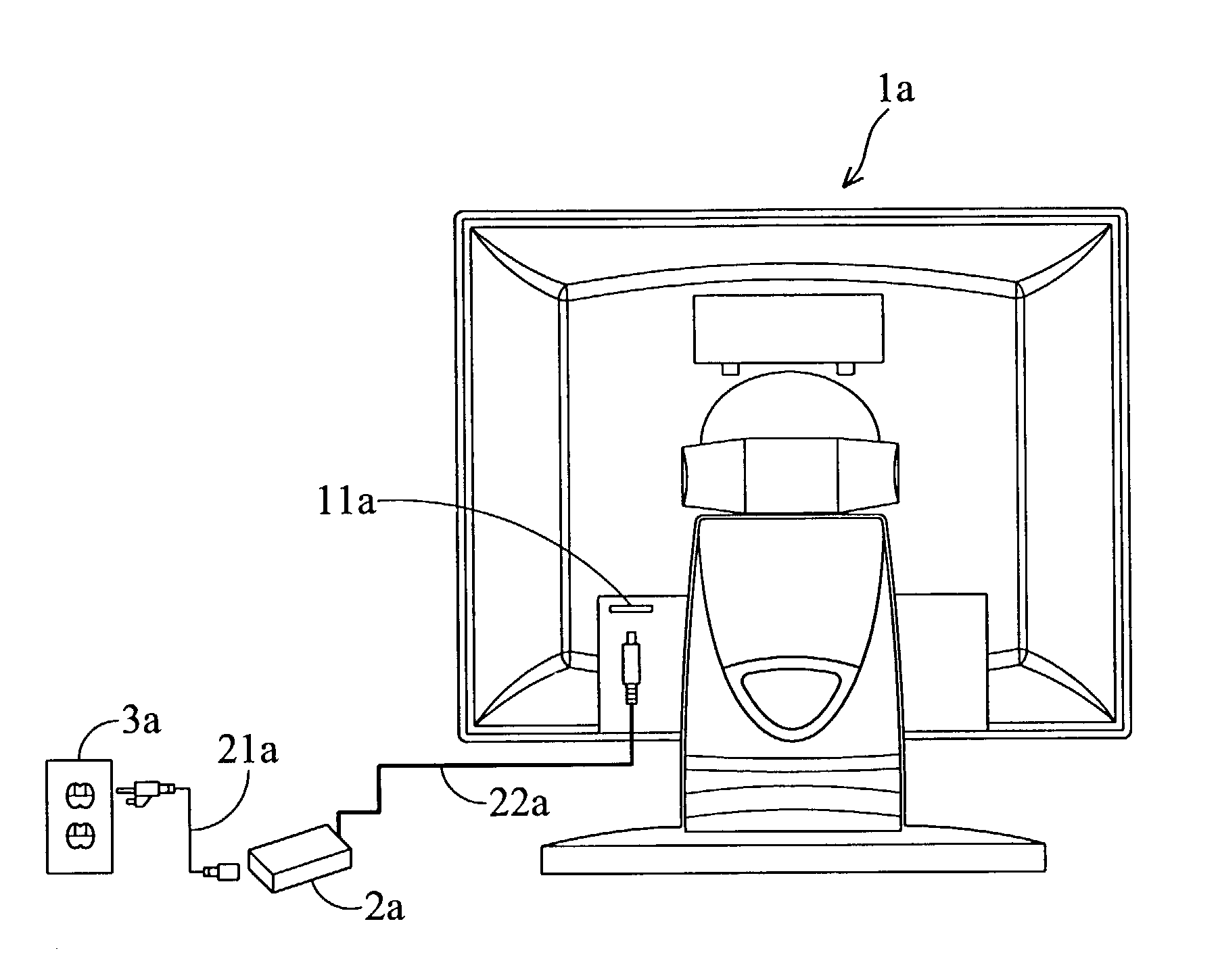
[0020]FIG. 2 is a schematic elevation diagram of a first embodiment according to the invention. As shown in FIG. 2, this embodiment is an LCD 1 with power conversion capability that implements a power conversion module 2 inside to essentially convert an input AC voltage into a stable output DC voltage. The input AC voltage is provided by a power line 3 plugging in a power socket 4. The output DC voltage is provided by a powering bus 11 coupled to a main board 12 in the LCD 1. The main board 12 is responsive of the LCD 1 display and other functions and supplies the required operating voltage through the power conversion module 2.

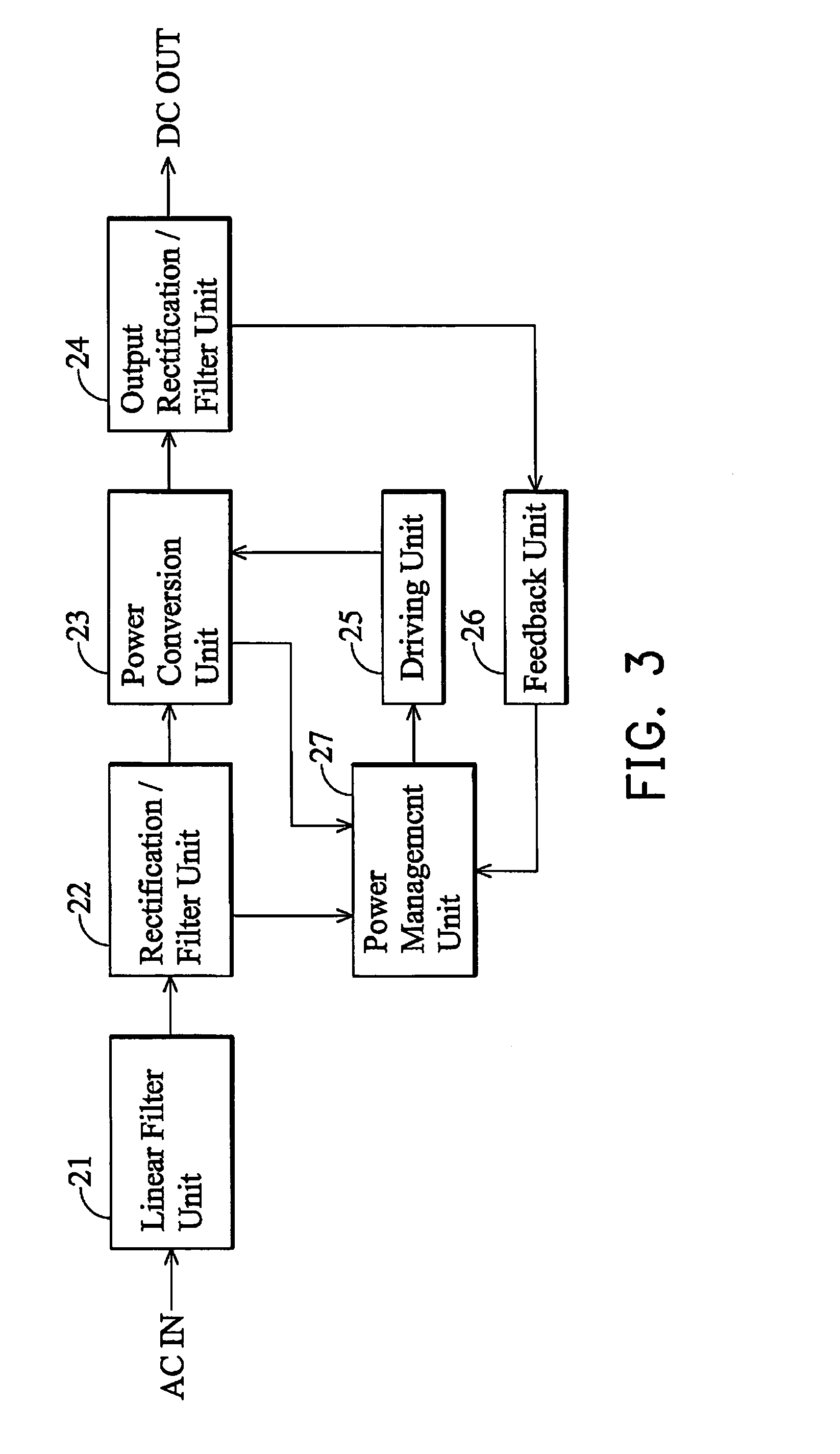
[0021]FIGS. 3 and 4 are diagrams of a power conversion module and its circuitry according to an exemplary embodiment of the invention. As shown in FIG. 3, the po...


PUM


Abstract

An LCD with power conversion capability. The LCD implements a power conversion model inside to convert AC input into DC operating voltage for the LCD. The power conversion model can provide functionalities of output voltage adjustment, voltage overload protection, output short-circuited protection and optimized DC conversion efficiency, thereby achieving the desired reliability.

Description

BACKGROUND OF THE INVENTION[0001]1. Field of the Invention[0002]The invention relates to an LCD, especially to an LCD capable of power conversion without relying on an external converter.[0003]2. Description of Related Art[0004]FIG. 1 is a schematically rear elevation diagram of a typical LCD connected to a power converter. As shown in FIG. 1, an LCD 1a currently has to be operated with the help of an external power converter 2a to convert supplied AC input into DC output. The external power converter 2a has a power line 21a with one end connected to a supplied socket 3a to receive the supplied AC input and the other end connected to a power plug 11a of the LCD 1a to power the LCD 1a. [0005]However, the converter 2a is implemented outside the LCD 1a. This limits operating space.[0006]Additionally, the LCD 1a and the converter 2a are generally fabricated by different manufacturers so that when the converter 2a is fabricated to be compatible with different LCD models, the retail price...

Claims


Application Information

Patent Timeline
IPC IPC(8): G09G5/00G09G3/36H02M3/335H02M5/00
CPCH02M3/335
Inventor KEE, YEW-PENG
Owner WISTRON CORP
Learn More