Magnetic recording head for perpendicular recording and including a portion protruding toward a mail pole and magnetic disc storage apparatus mounting the magnetic head

a technology of perpendicular recording and magnetic recording head, which is applied in the field of magnetic recording head, can solve the problems of increasing the maximum half width of the isolated pulse, narrowing the recording track width by increasing the recording density, etc., and achieves the reduction of the extent of deterioration of the reproduction resolution due to the curvature of the magnetic-transition pattern, the effect of improving the recording density and reducing the magnetic-transition width of the recording bits

Inactive Publication Date: 2006-05-30
WESTERN DIGITAL TECH INC +1
View PDF12 Cites 28 Cited by
  • Summary
  • Abstract
  • Description
  • Claims
  • Application Information

AI Technical Summary

Benefits of technology

[0028]The inventors realized, after calculating the recording magnetic field by three-dimensional computer simulation, that by using the recording head of the above-mentioned shape, the magnetic field distribution can be made linear in the direction of the track width and the curvature of the magnetic-transition pattern in the recording bit cells can be corrected. As the field distribution is made linear in the track width direction, the magnetic-transition width of the recording bits can be decreased, so that the extent of deterioration of the reproduction resolution due to the curvature of the magnetic-transition pattern can be reduced. By mounting the recording head, a magnetic disc apparatus with an improved recording density can be obtained.

Problems solved by technology

If the magnetic-transition pattern is curved with respect to the track direction, the magnetic transition width appears large upon reproduction with a GMR (giant magnet resistive) head or a TMR (tunneling magnetoresistive) head, for example, resulting in an increase in the maximum half width of the isolated pulse as well as the problem of the recording track width being narrowed by an increase in the track recording density.

Method used


Image

  • Magnetic recording head for perpendicular recording and including a portion protruding toward a mail pole and magnetic disc storage apparatus mounting the magnetic head
  • Magnetic recording head for perpendicular recording and including a portion protruding toward a mail pole and magnetic disc storage apparatus mounting the magnetic head
  • Magnetic recording head for perpendicular recording and including a portion protruding toward a mail pole and magnetic disc storage apparatus mounting the magnetic head

Examples


Embodiment Construction

[0041]The invention will be hereafter described by way of embodiments with reference made to the attached drawings.

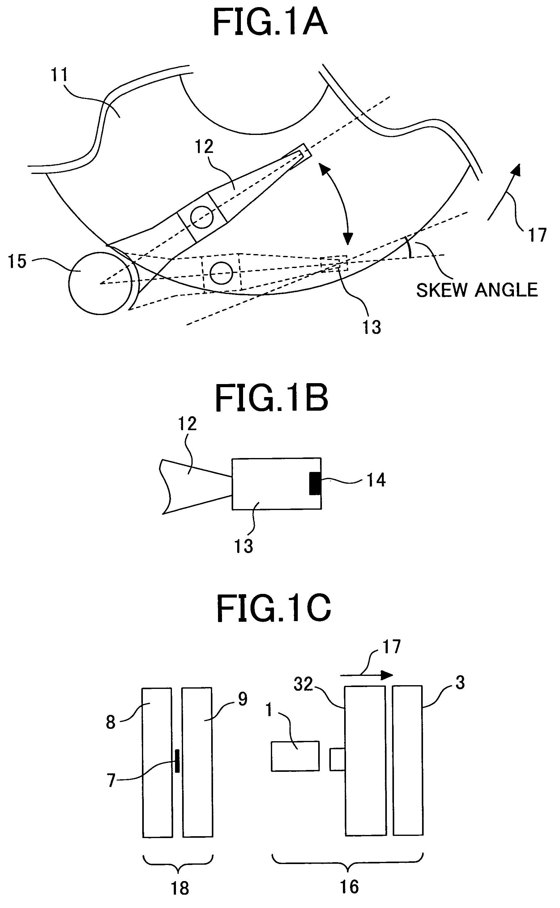
[0042]FIG. 1A schematically shows an example of the magnetic disc apparatus according to the invention. FIG. 1B is an enlarged view of a magnetic head slider portion of the apparatus. FIG. 1C is an enlarged view of a magnetic head portion of FIG. 1B as seen from the head air bearing surface.

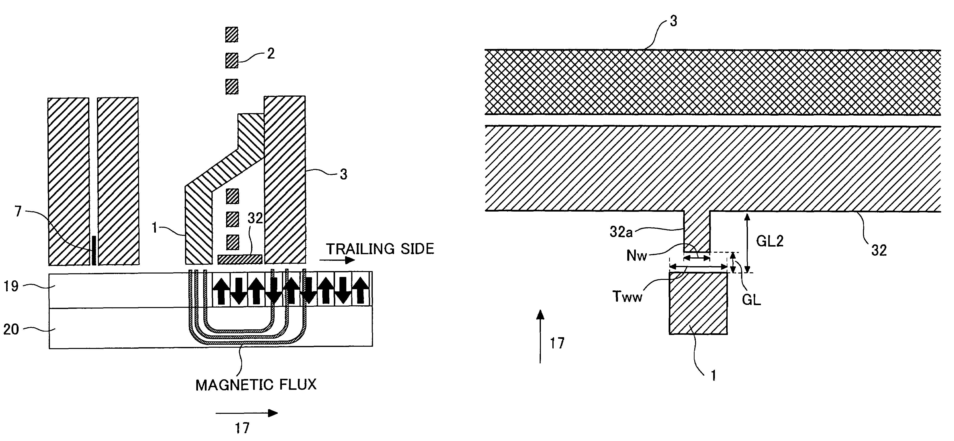
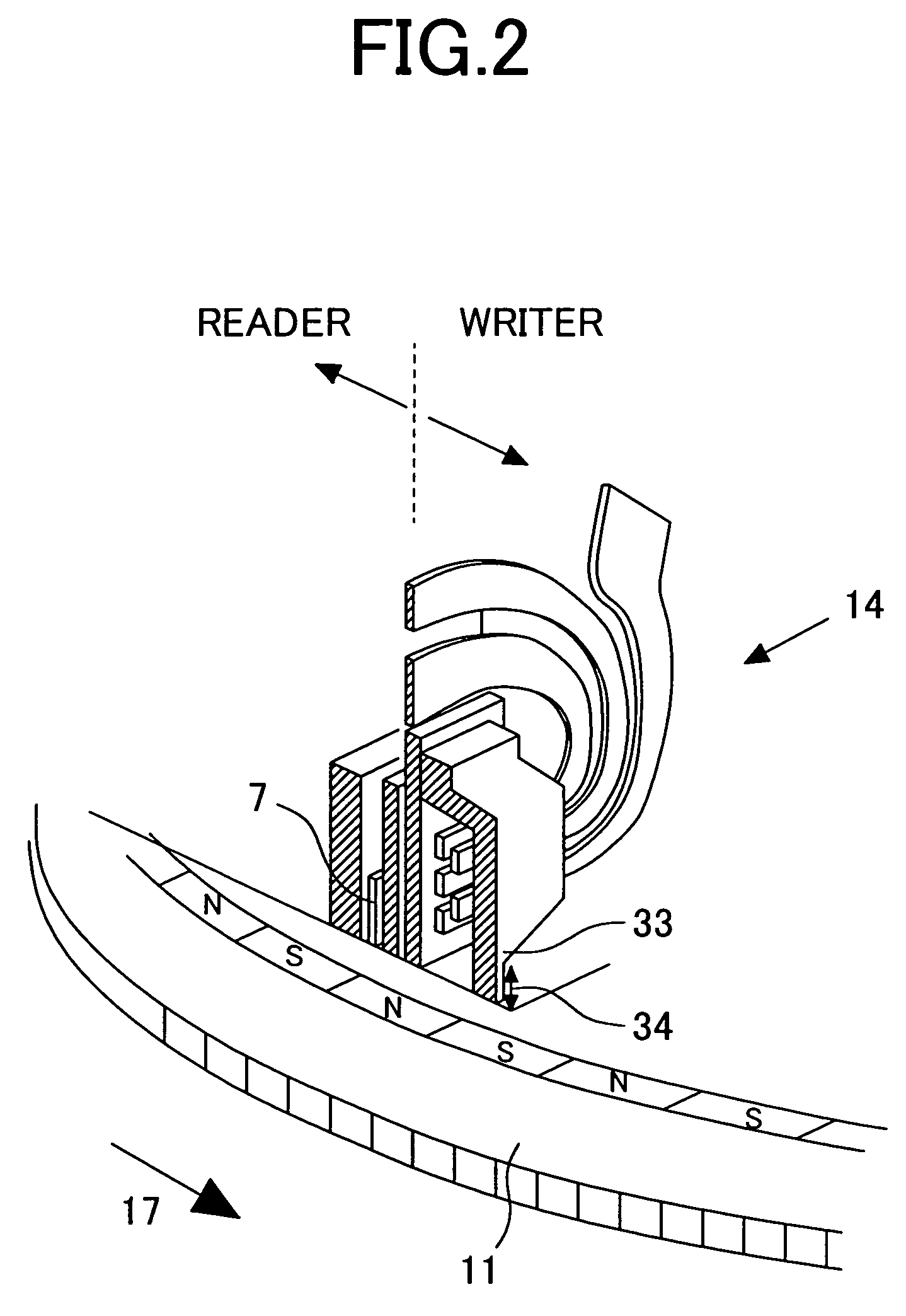
[0043]The magnetic disc apparatus carries out recording and reproduction of a magnetization signal on a magnetic disc 11 rotating in a direction of an arrow 17, using a magnetic head 14. The magnetic head 14 is mounted on a magnetic head slider 13 which is secured to the tip of a suspension arm 12 rotated by a rotary actuator 15. The magnetic head 14 is made up of a recording head 16 and a reproduction head 18. The reproduction head 18 includes a reproduction element 7 disposed between a lower shield 8 and an upper shield 9. The recording head 16 includes a main pole 1, an auxiliary ...


PUM

PropertyMeasurementUnit
saturated magnetic flux densityaaaaaaaaaa
widthaaaaaaaaaa

Abstract

A magnetic field distribution of a recording head is made linear so that a curvature of the magnetic-transition pattern in recording bit cells can be corrected. In a SPT head having a main pole 1 and an auxiliary pole 3, a magnetic layer 32 is disposed on a trailing side of the main pole. The magnetic layer is provided with a protruding portion 32a protruding towards the main pole. A width Nw of a side of the protruding portion opposite the main pole of the protruding portion is made smaller than a width Tww of the main pole on the trailing side.

Description

BACKGROUND OF THE INVENTION[0001]1. Technical Field[0002]The present invention relates to a magnetic head suitable for perpendicular magnetic recording, a process of manufacturing the magnetic head, and a magnetic disc apparatus mounting the magnetic head.[0003]2. Background Art[0004]In magnetic disc apparatuses, data on a recording medium is read and written using a magnetic head. In order to increase the recording volume per unit area on a magnetic disc, areal density must be increased. In the current longitudinal recording systems, however, as the length of bits that are recorded decreases, the areal density cannot be increased due to thermal fluctuations in the magnetization in the medium. To solve this problem, a perpendicular recording system has been proposed whereby a magnetization signal is recorded in a direction perpendicular to the medium.[0005]There are two types of perpendicular magnetic recording. One employs a double-layer perpendicular magnetic recording medium comp...

Claims


Application Information

Patent Timeline
Patent Type & Authority Patents(United States)
IPC IPC(8): G11B5/187G11B5/00G11B5/31G11B5/012G11B5/09G11B5/127G11B5/23G11B5/48
CPCG11B5/012G11B5/1278G11B5/23G11B5/1871G11B5/09G11B2005/0029G11B5/4886
Inventor MOCHIZUKI, MASAFUMINAKAMURA, ATSUSHIETOH, KIMITOSHI
Owner WESTERN DIGITAL TECH INC
Why Eureka
Try Eureka