Clock switch device and microcontroller for selecting one of a plurality of clocks based on signal levels

Active Publication Date: 2006-05-30
COLLABO INNOVATIONS INC
View PDF4 Cites 7 Cited by
  • Summary
  • Abstract
  • Description
  • Claims
  • Application Information

AI Technical Summary

Benefits of technology

[0030]With the above configuration, in switching of a clock according to clock selection data determined by software, it is possible not to select a ...

Problems solved by technology

The conventional clock switch device described above has the following problem at the time of clock sw...

Method used


Image

  • Clock switch device and microcontroller for selecting one of a plurality of clocks based on signal levels
  • Clock switch device and microcontroller for selecting one of a plurality of clocks based on signal levels
  • Clock switch device and microcontroller for selecting one of a plurality of clocks based on signal levels

Examples


embodiment 1

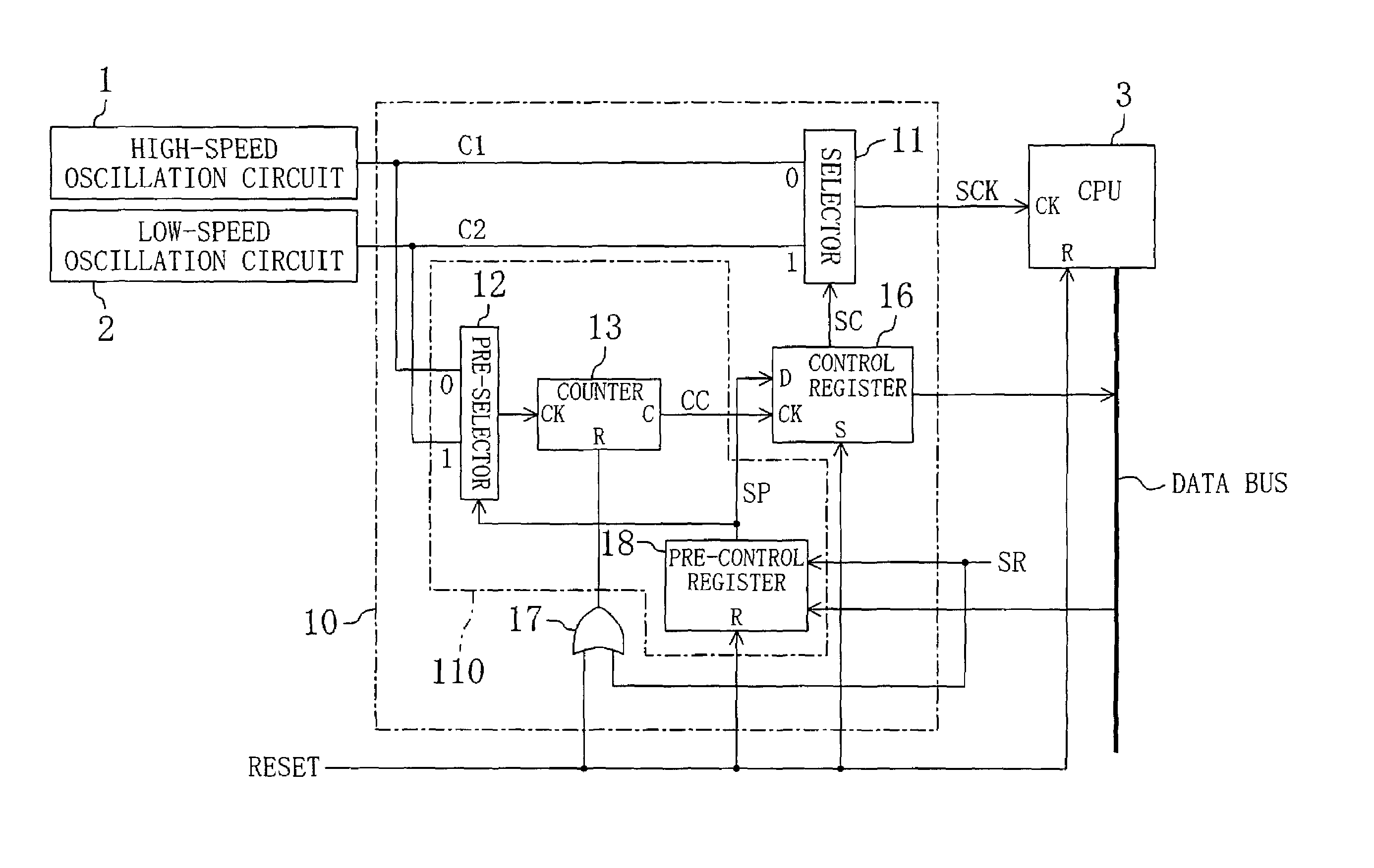
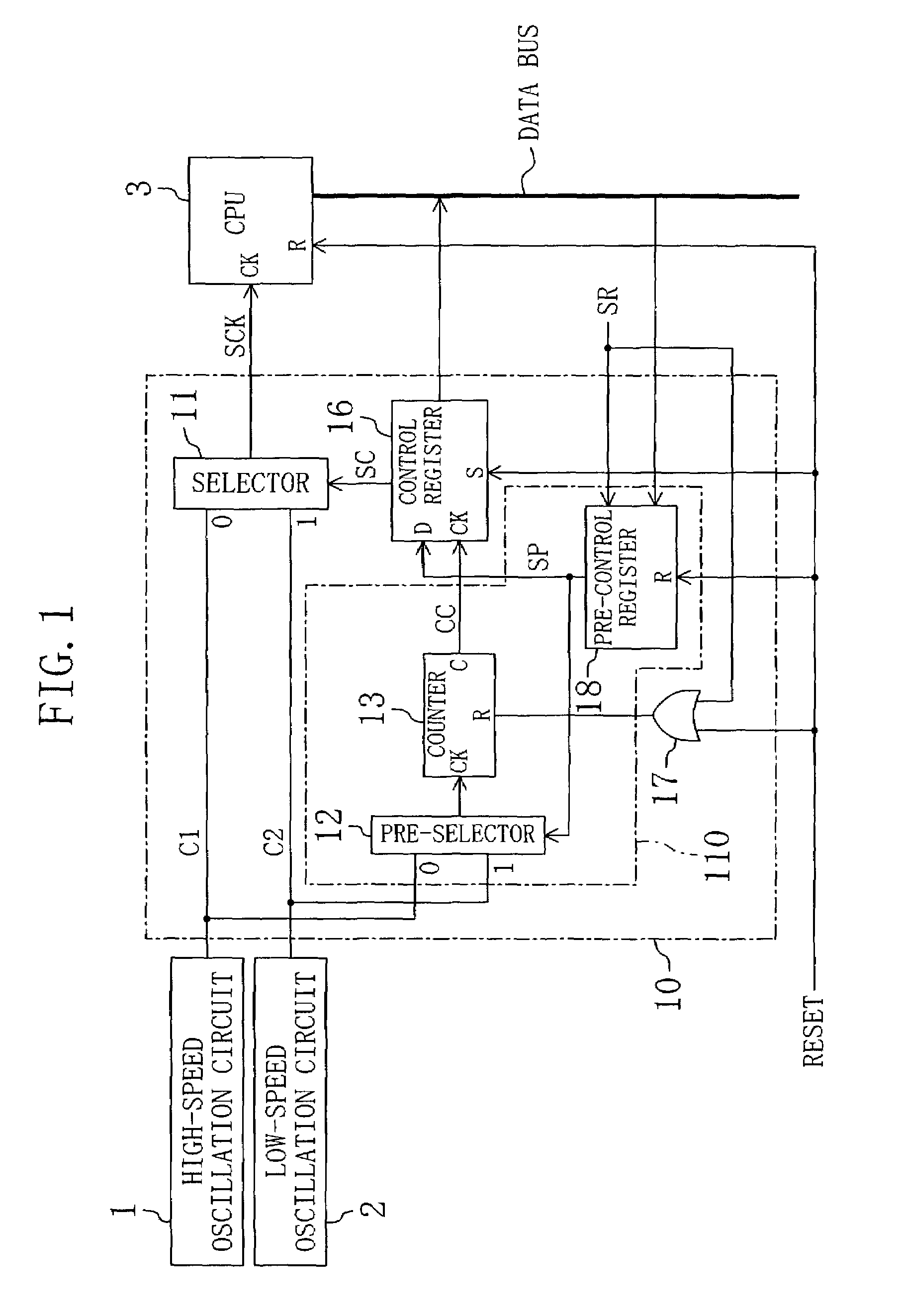
[0041]FIG. 1 is a block diagram of a microcontroller including a clock switch device of Embodiment 1 of the present invention. The microcontroller of FIG. 1 includes a high-speed oscillation circuit 1, a low-speed oscillation circuit 2, a CPU 3 and a clock switch device 10. The clock switch device 10 includes a selector 11, a pre-selector 12, a counter 13, a control register 16, an OR gate 17 and a pre-control register 18. The pre-selector 12, the counter 13 and the pre-control register 18 constitute a clock detector 110.

[0042]Each of the high-speed oscillation circuit 1 and the low-speed oscillation circuit 2 is configured to be connectable with an external crystal. When one of the high-speed oscillation circuit 1 and the low-speed oscillation circuit 2 is not necessary to operate, the non-operating oscillation circuit is not connected with the external crystal.

[0043]The high-speed oscillation circuit 1 outputs a high-speed clock C1 to the selector 11 and the pre-selector 12. The l...

first alteration to embodiment 1

[0070]FIG. 6 is a block diagram of a microcontroller including a clock switch device of the first alteration to Embodiment 1 of the present invention. The microcontroller of FIG. 6 includes a high-speed oscillation circuit 1, a low-speed oscillation circuit 2, a CPU 3 and a clock switch device 20. The clock switch device 20 in FIG. 6 is different from the clock switch device 10 in FIG. 1 in that counters 23 and 24 and a counter output selector 25 are used in place of the counter 13. The other components are substantially the same as those described in Embodiment 1. The pre-selector 12, the pre-control register 18, the counters 23 and 24 and the counter output selector 25 constitute a clock detector 120.

[0071]The counters 23 and 24 are connected in series. That is, the counter 24 receives an overflow signal output from the counter 23. The counter 23, the first-stage counter of the serially connected counters 23 and 24, receives the output of the pre-selector 12. The counters 23 and 2...

second alteration to embodiment 1

[0077]FIG. 7 is a block diagram of a microcontroller including a clock switch device of the second alteration to Embodiment 1 of the present invention. The microcontroller of FIG. 7 includes a high-speed oscillation circuit 1, a low-speed oscillation circuit 2, a CPU 3 and a clock switch device 30. The clock switch device 30 in FIG. 7 is different from the clock switch device 10 in FIG. 1 in that a programmable counter 33 is used in place of the counter 13 and the OR gate 17. The other components are substantially the same as those described in Embodiment 1. The pre-selector 12, the pre-control register 18 and the programmable counter 33 constitute a clock detector 130.

[0078]The programmable counter 33 receives a counter set value output from the CPU 3 via the data bus and also receives a load request signal LR. The load request signal LR is a signal generated based on an address output from the CPU 3, obtained by decoding an address bus (not shown). The programmable counter 33 is r...


PUM


Abstract

The clock switch device of the present invention includes: a clock detector for receiving a plurality of clocks and clock selection data designating a clock to be selected, detecting whether or not the clock designated by the clock selection data among the plurality of clocks changes in signal level, and outputting the result as a detection signal; a control register for holding and outputting the clock selection data when the detection signal indicates that the clock designated by the clock selection data changes in signal level; and a selector for receiving the plurality of clocks and selecting a clock corresponding to the output of the control register among the plurality of clocks.

Description

BACKGROUND OF THE INVENTION[0001]The present invention relates to semiconductor integrated circuits such as microcontrollers.[0002]There are known microcontrollers that receive a high-speed clock output from a high-speed oscillation circuit and a low-speed clock output from a low-speed oscillation circuit and select one of these clocks for use as the current clock. In this type of microcontrollers, the clock can be switched by software during operation, to realize high-speed operation by selecting the high-speed clock or low power consumption by selecting the low-speed clock.[0003]When it is not necessary to use one of the high-speed oscillation circuit or the low-speed oscillation circuit, the unused oscillation circuit is often blocked from connection with an external crystal and the like, to reduce the cost for external components. A microcontroller adopting this method is provided with a circuit for selecting the output of an oscillation circuit in operation as the clock at the ...

Claims


Application Information

Patent Timeline
IPC IPC(8): G06F1/06G06F1/08G06F1/04H03K5/19
CPCH03K5/19G06F1/08
Inventor SHINKAWA, KAZUAKI
Owner COLLABO INNOVATIONS INC
Why Eureka
Try Eureka