Safety system for power equipment

a safety system and power equipment technology, applied in the field of safety systems, can solve the problems of affecting the operation of metal sawing accessories and affecting the safety of power equipmen

Inactive Publication Date: 2006-06-06
SAWSTOP HLDG LLC
View PDF445 Cites 156 Cited by
  • Summary
  • Abstract
  • Description
  • Claims
  • Application Information

AI Technical Summary

Problems solved by technology

Unfortunately, the power and high operating speeds of mechanized equipment creates a risk for those operating such machinery.
Each year thousands of people are maimed or killed by accidents involving power equipment.
In many cases, guards are effective to reduce the risk of injury, however, there are many instances where the nature of the operations to be performed precludes using a guard that completely blocks access to hazardous machine parts.
These systems interrupt or reverse power to the motor, or disengage a clutch, upon contact with a user's hand by any dangerous portion of the machine.
Although such systems are suitable for use with meat skinning machines, they are relatively slow to stop the motion of the cutting element because they rely on the operation of solenoids or must overcome the inertia of the motor.
Unfortunately, such a system is prone to false triggers and is relatively slow acting because of the solenoid.
However, the system described for detecting blade contact does not appear to be functional to accurately and reliably detect contact.
Therefore, the system is too slow to stop the blade quickly enough to avoid serious injury.
None of these existing systems have operated with sufficient speed and / or reliability to prevent serious injury with many types of commonly used power tools.
As a result, existing proximity-type sensors, which are relatively imprecise, have not proven effective with this type of equipment.
Even where proximity sensors are practical, existing brake systems have not operated quickly enough to prevent serious injury in many cases.
This distance is more than sufficient to result in the loss of several digits, severing of vital vessels and tendons, or even complete severing of a hand.
Standard solenoids or other electromagnetic devices are generally not designed to act in this time scale, particularly where significant force must be generated.

Method used


Image

  • Safety system for power equipment
  • Safety system for power equipment
  • Safety system for power equipment

Examples


Embodiment Construction

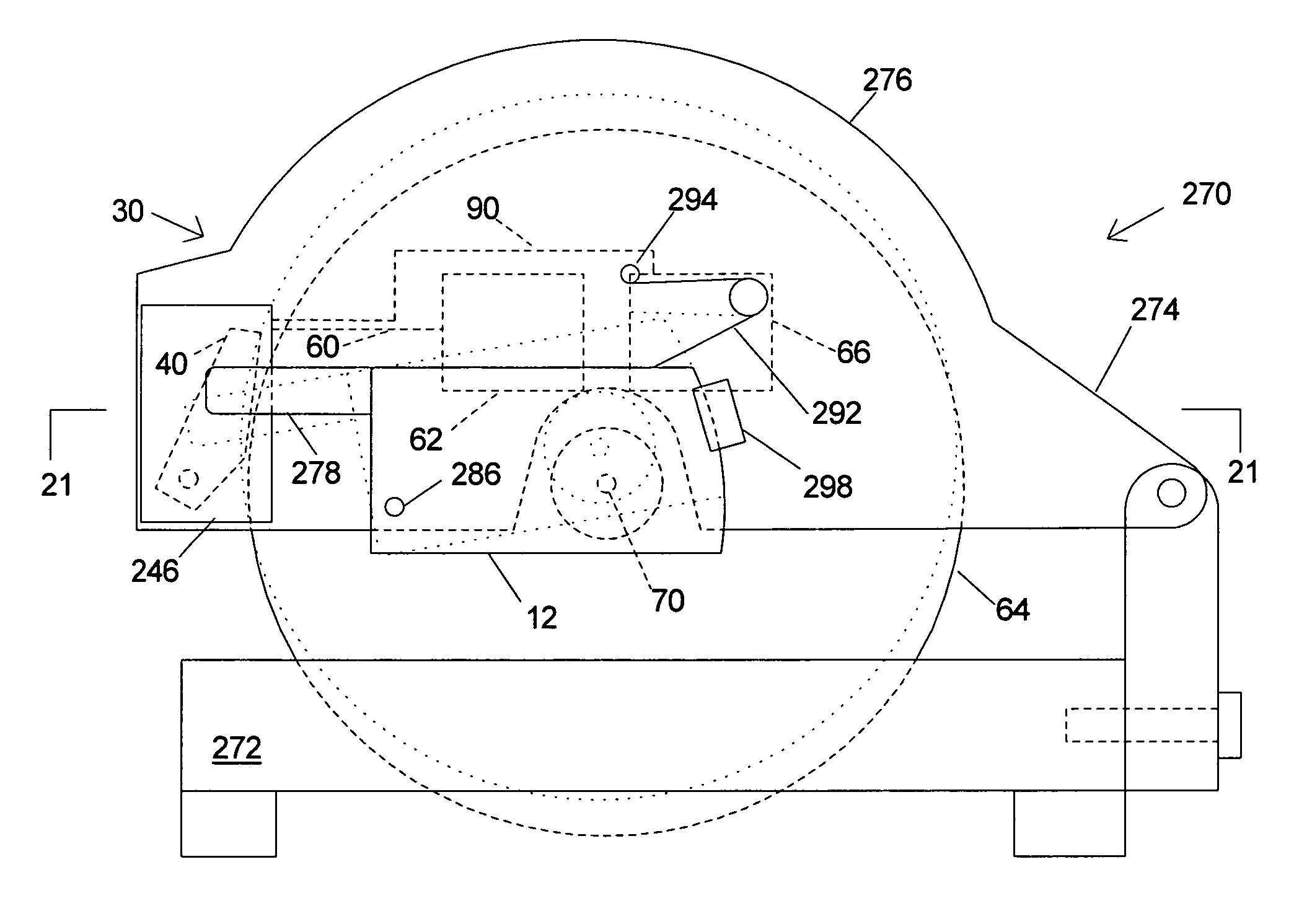
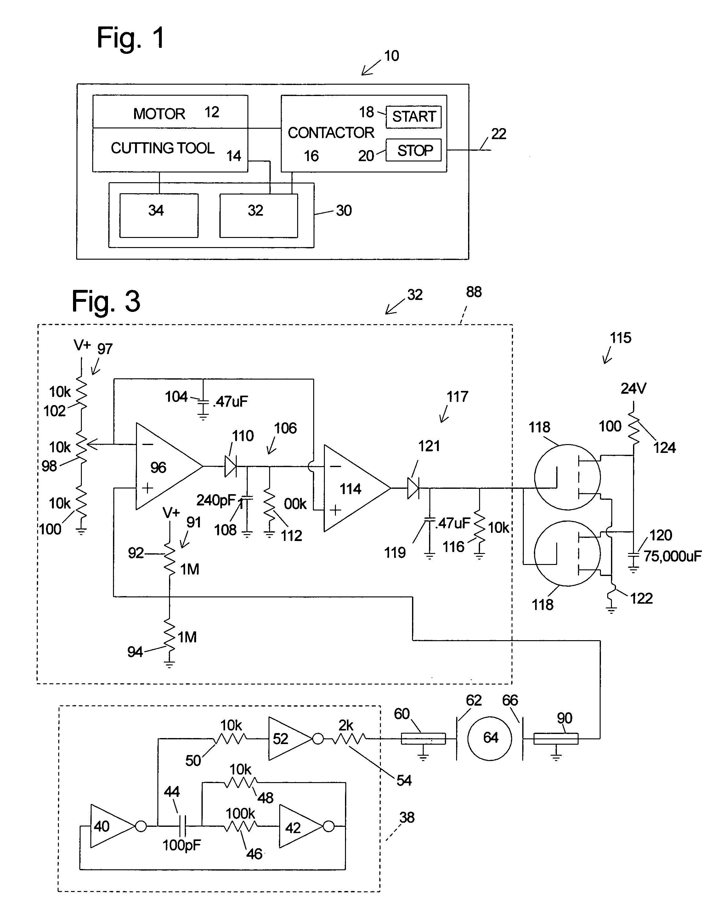
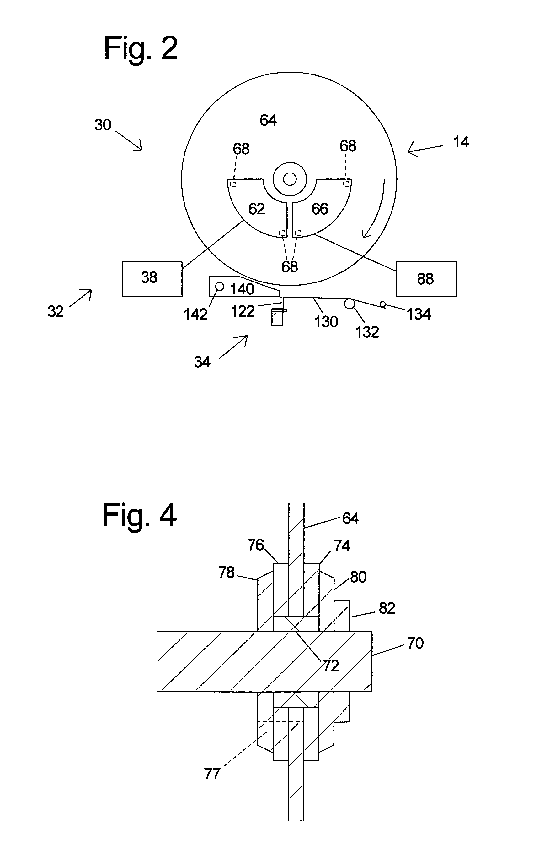
[0038]A machine according to the present invention is shown schematically in FIG. 1 and indicated generally at 10. Machine 10 includes a motor assembly 12 adapted to drive a cutting tool 14. Motor assembly 12 includes one or more motors, at least one of which is adapted to drive cutting tool 14. For example, machine 10 may include one or more motors adapted to drive tool 14 as well as one or more motors adapted to feed work pieces, such as wood, into contact with the cutting tool. Cutting tool 14 typically includes one or more blades or other suitable cutting implements that are adapted to cut or remove portions from the work pieces. The particular form of cutting tool 14 will tend to vary depending upon the various embodiments of machine 10. For example, in table saws, chop and miter saws, circular saws and radial arm saws, cutting tool 14 will typically include a circular rotating blade having a plurality of teeth disposed along the perimetrical edge of the blade. For a jointer or...


PUM

PropertyMeasurementUnit
capacitanceaaaaaaaaaa
voltage amplitudeaaaaaaaaaa
areasaaaaaaaaaa

Abstract

Safety systems for power equipment are disclosed. The safety systems include a detection system adapted to detect contact between a person and a working portion of a machine, where the detection system is adapted to capacitively impart an electric charge on the working portion and to detect when that charge drops; and a reaction system associated with the detection system to cause a predetermined action to take place relative to the working portion upon detection of contact between the person and the working portion by the detection system. Machines equipped with safety systems are also disclosed, such as saws, jointers, etc. The machines include a working portion, such as a cutter or blade, a detection system adapted to detect a dangerous condition between a person and the working portion, and a reaction system associated with the detection system to cause a predetermined action to take place upon detection of the dangerous condition, such as a brake system to stop the working portion, a retraction system to retract the working portion, or a system to cover the working portion. The machines may include a control system adapted to control the operability of one or more of the working portion, the detection system and the reaction system.

Description

CROSS-REFERENCE TO RELATED APPLICATIONS[0001]This application claims the benefit of and priority from U.S. Provisional Patent Application Ser. No. 60 / 157,340, filed Oct. 1, 1999 and U.S. Provisional Patent Application Ser. No. 60 / 182,866, filed Feb. 16, 2000, both of which are hereby incorporated by reference.FIELD OF THE INVENTION[0002]The present invention relates to safety systems and more particularly to a high-speed safety stop for use on power equipment.BACKGROUND OF THE INVENTION[0003]Beginning with the industrial revolution and continuing to the present, mechanized equipment has allowed workers to produce goods with greater speed and less effort than possible with manually-powered tools. Unfortunately, the power and high operating speeds of mechanized equipment creates a risk for those operating such machinery. Each year thousands of people are maimed or killed by accidents involving power equipment.[0004]As might be expected, many systems have been developed to minimize the...

Claims


Application Information

Patent Timeline
Patent Type & Authority Patents(United States)
IPC IPC(8): B26D5/00B26D1/14
CPCB23D59/001B27B5/38B27G19/02H01H3/022H01H27/00F16P3/12Y10S83/01H01H9/161Y10T83/081Y10T83/089Y10T83/175Y10T83/178Y10T83/7726Y10T83/773Y10T83/7788
Inventor GASS, STEPHEN F.
Owner SAWSTOP HLDG LLC
Why Eureka
Try Eureka