Gas cleaning system and method

a cleaning system and gas technology, applied in the direction of combustible gas purification/modification, energy input, synthetic resin layered products, etc., can solve the problems of high cost of disposal of cleaning process byproducts, high contamination of water, and large amount of treatmen

Inactive Publication Date: 2006-06-06
SIEMENS ENERGY INC
View PDF14 Cites 44 Cited by
  • Summary
  • Abstract
  • Description
  • Claims
  • Application Information

AI Technical Summary

Problems solved by technology

The production of syngas can create substantial polluting emissions, such as, but not limited to, H2S and CO2.
Conventional gas cleaning technologies are often used to remove these contaminants; however, disposal of the byproducts of the cleaning process can be expensive.
This operation generates highly contaminated water requiring considerable treatment.
However, the Rectisol process requires a substantial investment in equipment and incurs high power costs.
In addition, the Rectisol process effectively and undesirably for IGCC removes CO2 from the syngas.
Reheating the syngas consumes energy and is inefficient.
However, most are expensive to construct and operate.
In addition, most systems require complex water treatment systems to remove the contaminants from the water generated during the cleaning process.
Moreover, many of the conventional systems result in “drying” of the gas and partial CO2 removal, which results in an energy loss that is not acceptable for some applications.
In addition, conventional syngas often contains products that can harm power generation in IGCC applications such as metal cabonyls and particles from corrosion of the syngas pipes.
In particular, these products can be deposited in the turbines and can cause erosion damage in the turbines.

Method used


Image

  • Gas cleaning system and method
  • Gas cleaning system and method
  • Gas cleaning system and method

Examples


Embodiment Construction

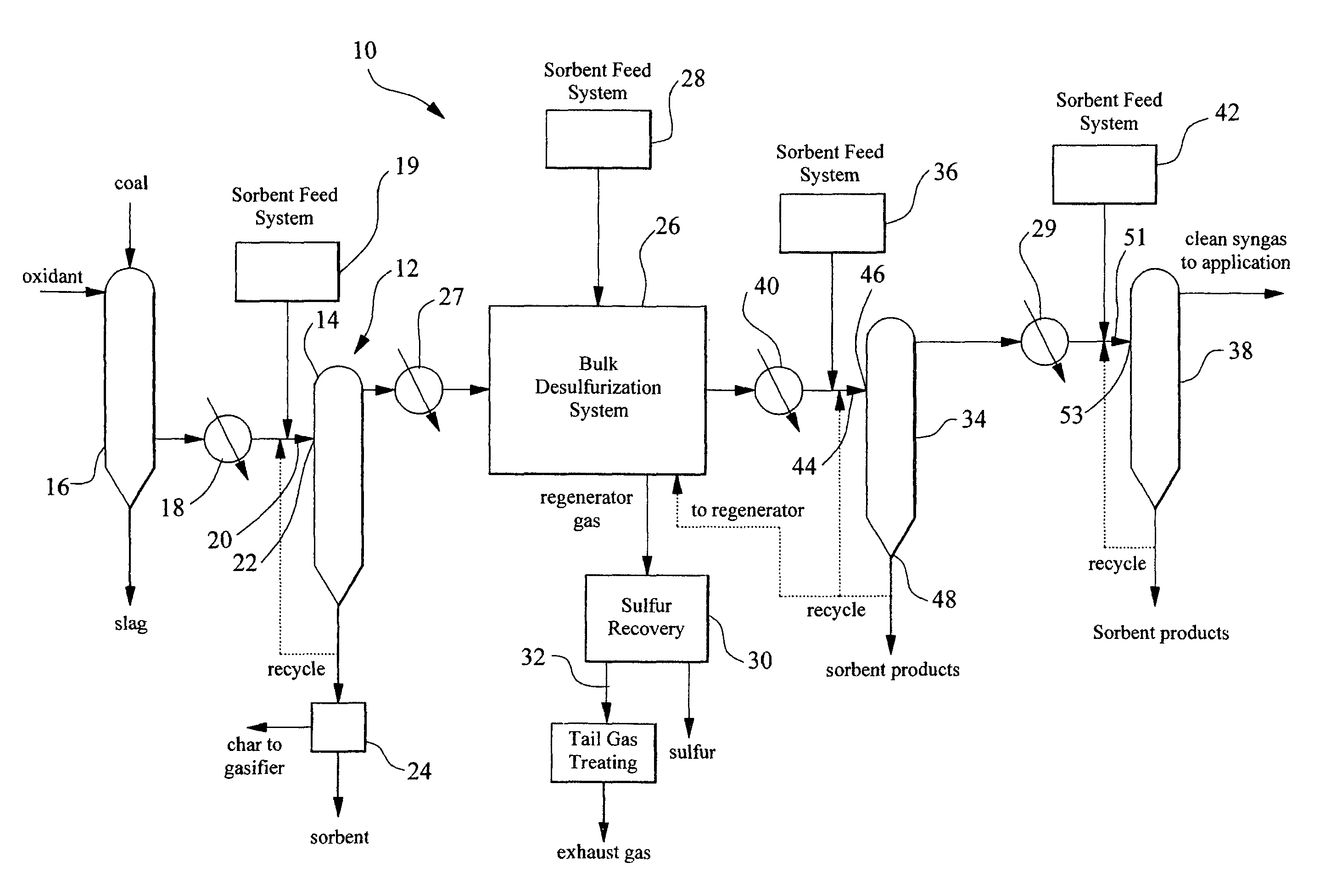
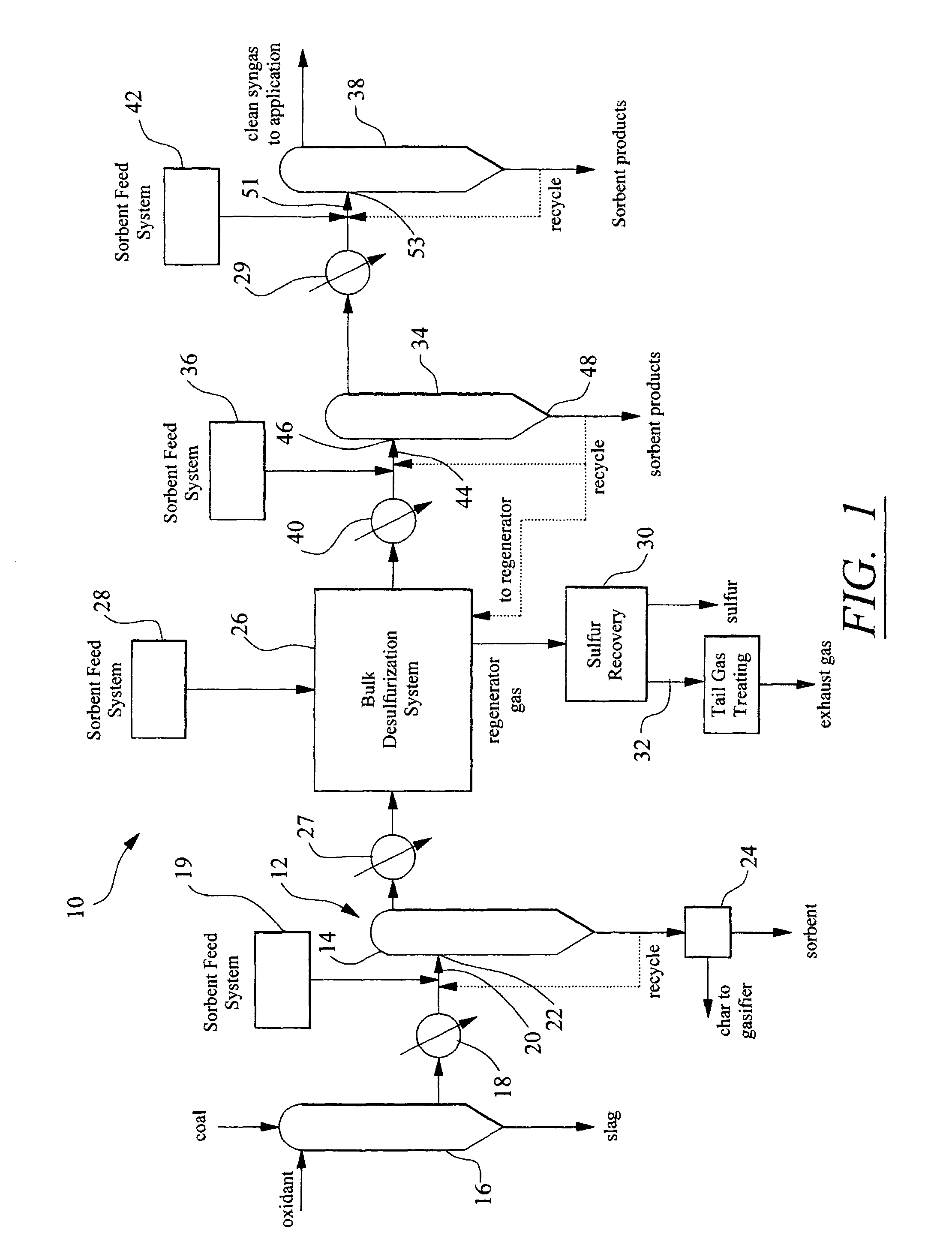
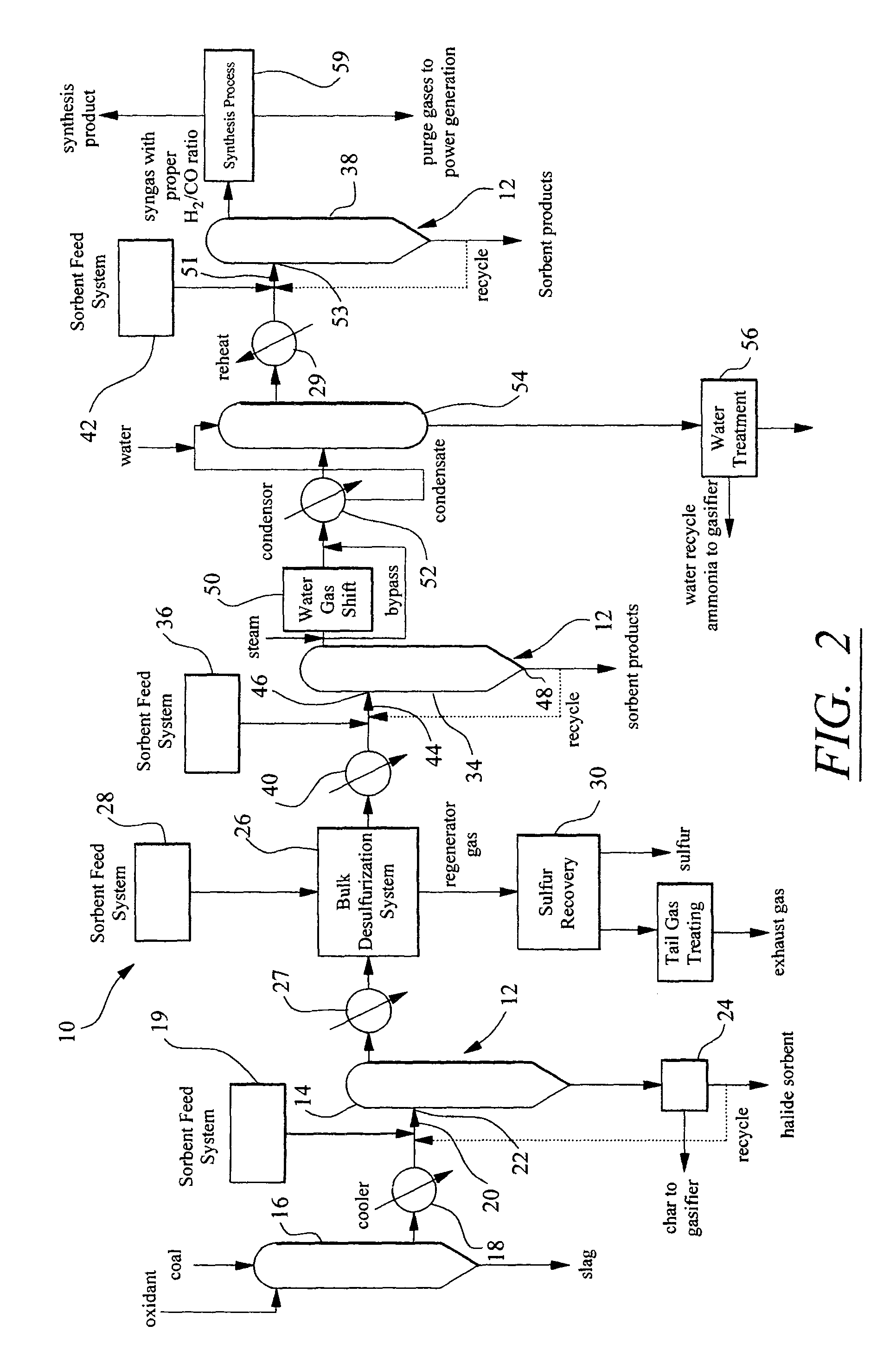
[0025]As shown in FIGS. 1–3, this invention is directed to systems and methods for cleaning feedstock gas, such as syngas or other gases. Syngas may be defined as any gas produced through gasification of a biomass, such as, but not limited to, coal, oil and natural gas, by the application of high temperature and steam. In particular, in at least one embodiment, the systems and methods may reduce concentrations of halides, sulfur, particulate, and mercury contained in the feedstock gas to levels at or below governing guidelines. Feedstock gas may be produced for a variety of applications, such as, but not limited to: synthesis of chemicals, such as, but not limited to, methanol, ammonia, and hydrogen; fuel cell power generation; IGCC power generation; and the like.

[0026]As shown in FIGS. 1–3, the gas cleaning system 10 may include a plurality of filter vessels 12 for removing one or more of the constituents previously mentioned or others from feedstock gas. The filter vessels 12 may ...


PUM

PropertyMeasurementUnit
temperatureaaaaaaaaaa

Abstract

A gas cleaning system for removing at least a portion of contaminants, such as halides, sulfur, particulates, mercury, and others, from a synthesis gas (syngas). The gas cleaning system may include one or more filter vessels coupled in series for removing halides, particulates, and sulfur from the syngas. The gas cleaning system may be operated by receiving gas at a first temperature and pressure and dropping the temperature of the syngas as the gas flows through the system. The gas cleaning system may be used for an application requiring clean syngas, such as, but not limited to, fuel cell power generation, IGCC power generation, and chemical synthesis.

Description

STATEMENT REGARDING FEDERALLY SPONSORED RESEARCH[0001]Development of this invention was supported in part by the United States Department of Energy, Contract No. DE-AC26-99FT40674. Accordingly, the United States Government may have certain rights in this invention.FIELD OF THE INVENTION[0002]This invention is directed generally to gas cleaning systems and processes, and more particularly to gas cleaning systems and processes for cleaning synthesis gas.BACKGROUND[0003]Many industrial processes use synthesis gas, which is otherwise known as syngas, for power generation, chemical synthesis, or other applications. Syngas primarily consists of hydrogen gas and carbon monoxide. Syngas can be produced from most kinds of hydrocarbon, including, but not limited to coal, oil and natural gas, by the application of high temperature and steam. Syngas can be burned, separated into carbon monoxide and hydrogen, or converted to a liquid fuel by processes like the Fischer-Tropsch process. In additio...

Claims


Application Information

Patent Timeline
Patent Type & Authority Patents(United States)
IPC IPC(8): C01B3/24B01D53/50B01D53/68B32B27/02B01D53/10C10K1/02C10K1/20C10K1/32C10K3/04H01M8/06
CPCB01D53/10C10K1/20C10K1/32C10K3/04C10K1/024B01D2257/204B01D2257/30B01D2257/602H01M8/0662Y02E60/50Y02P20/129
Inventor NEWBY, RICHARD ALLEN
Owner SIEMENS ENERGY INC
Why Eureka
Try Eureka