Communication apparatus and communication method

a technology of communication apparatus and communication method, applied in the field of communication apparatus, can solve the problems of invariably adjusting the characteristics of analog elements, carrying out measurements, and difficult to accurately and time-invariably carrying out measurements, so as to reduce the size and cost of the apparatus

Inactive Publication Date: 2006-06-06
PANASONIC CORP
View PDF20 Cites 28 Cited by
  • Summary
  • Abstract
  • Description
  • Claims
  • Application Information

AI Technical Summary

Benefits of technology

[0044]It is a second object of the present invention to provide a communication apparatus and communication method capable of correcting amplitude and phase shifts of the reception baseband signals and AGC signals without interrupting communications with other apparatuses and reducing the size and cost of the apparatus.
[0045]Th

Problems solved by technology

However, it is extremely difficult to accurately and time-invariably adjust the characteristics of analog elements such as amplifiers 15 and 16.
However, the conventional apparatus has a problem that it is unable, during transmission, to carry out a measurement to find characteristic errors of transmit power amplifiers 15 and 16 necessary to correct amplitude and phase shifts of the transmission signal during a communication with the mobile station apparatus and the communication must be interrupted to carry out the measurement.
Likewise, the conventional apparatus has another problem that it is unable, during reception, to carry out a measurement to find characteristic errors of radio apparatu

Method used


Image

  • Communication apparatus and communication method
  • Communication apparatus and communication method
  • Communication apparatus and communication method

Examples


embodiment 1

(Embodiment 1)

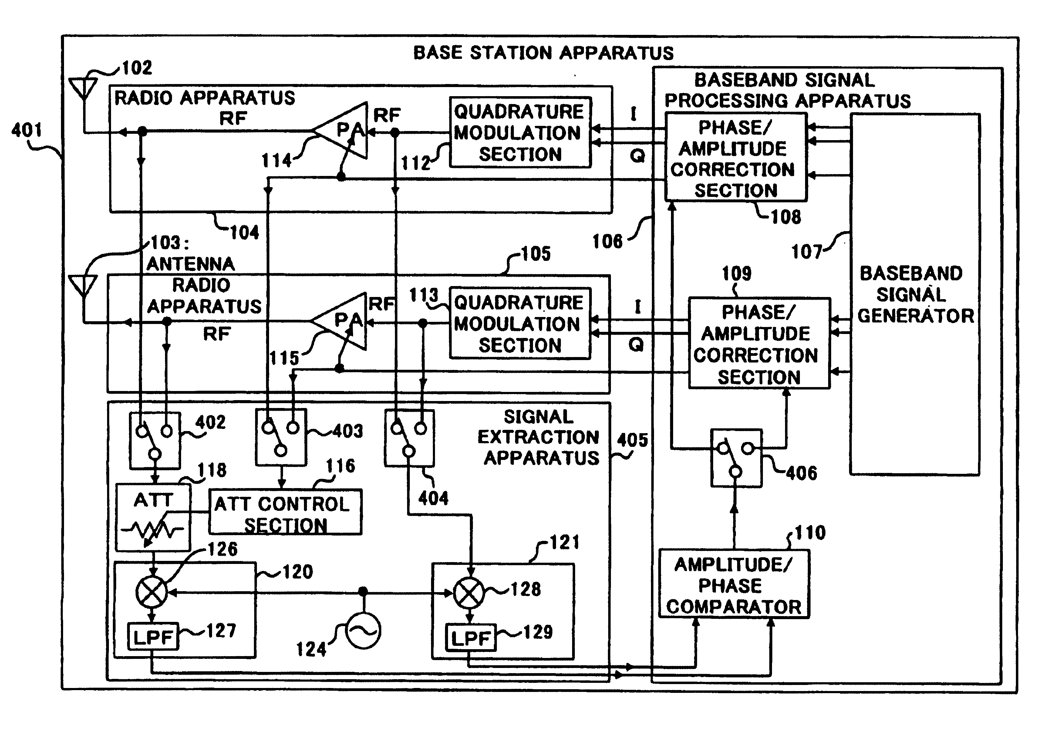
[0066]FIG. 3 is a block diagram showing a configuration on the transmitting side of a base station apparatus according to Embodiment 1 of the present invention.

[0067]Base station apparatus 101 shown in FIG. 3 has a configuration equipped with an array antenna made up of two antennas 102 and 103, radio apparatuses 104 and 105 with antennas 102 and 103 connected thereto and baseband signal processing apparatus 106.

[0068]On the other hand, baseband signal processing apparatus 106 has a configuration equipped with baseband signal generator 107, phase / amplitude correction sections 108 and 109 in a digital circuit configuration equipped with a D / A conversion circuit, which is not shown, at the signal output to radio apparatuses 104 and 105, and amplitude / phase comparators 110 and 111 in a digital circuit configuration equipped with an A / D conversion circuit, which is not shown, at the signal input from radio apparatuses 104 and 105.

[0069]Radio apparatuses 104 and 105 have a ...

embodiment 2

(Embodiment 2)

[0086]Embodiment 2 describes a case where up-conversion up to an intermediate frequency (IF) band is carried out first and then up-conversion up to a radio frequency (RF) band is carried out.

[0087]FIG. 4 is a block diagram showing a configuration on the transmitting side of a base station apparatus according to Embodiment 2 of the present invention. However, the components of base station apparatus 201 in FIG. 4 common to those of base station apparatus 101 in FIG. 3 are assigned the same reference numerals and explanations thereof will be omitted.

[0088]When compared to base station apparatus 101 in FIG. 3, base station apparatus 201 in FIG. 4 adopts a configuration equipped with quadrature modulation sections 202 and 203 instead of quadrature modulation sections 112 and 113. Furthermore, base station apparatus 201 in FIG. 4 also adopts a configuration with RF modulation sections 204 and 205 and oscillation sections 206 and 207 added to base station apparatus 101 in FI...

embodiment 3

(Embodiment 3)

[0095]Embodiment 3 describes a case where quadrature modulations 302 and 303 are configured by analog elements.

[0096]FIG. 5 is a block diagram showing a configuration on the transmitting side of a base station apparatus according to Embodiment 3 of the present invention. However, the components of base station apparatus 301 in FIG. 5 common to those of base station apparatus 101 in FIG. 3 are assigned the same reference numerals and explanations thereof will be omitted.

[0097]When compared to base station apparatus 101 in FIG. 3, base station apparatus 301 in FIG. 5 adopts a configuration equipped with quadrature modulation sections 302 and 303 configured by analog elements instead of quadrature modulation sections 112 and 113. Furthermore, base station apparatus 301 in FIG. 5 adopts a configuration with frequency conversion sections 121 and 123 removed and amplitude / phase comparators 304 and 305 added instead of amplitude / phase comparators 110 and 111 to base station a...


PUM


Abstract

Baseband signal generator 107 outputs a transmission baseband signal with a coefficient for setting antenna directivity multiplied and a gain control signal to transmit power amplifier 114 and transmit power amplifier 114 amplifies the transmission baseband signal with a gain corresponding to the gain control signal and transmits the signal from antenna 102. ATT 118 attenuates the output signal of amplifier 114 according to the gain control signal, amplitude/phase comparator 110 calculates amplitude and phase errors between the attenuated signal with a frequency equalized by frequency conversion sections 120 and 121 and the input signal of amplifier 114 and phase/amplitude correction section 108 corrects the transmission baseband signal and gain control signal so as to eliminate the errors. This makes it possible to correct the amplitude and phase shifts of the transmission signal during a communication with other apparatuses and reduce the size and cost of the apparatus.

Description

TECHNICAL FIELD[0001]The present invention relates to a communication apparatus such as a base station apparatus in a mobile communication system, and more particularly, to a communication apparatus equipped with an array antenna.BACKGROUND ART[0002]An example of a communication apparatus and communication method equipped with an array antenna is described in the Unexamined Japanese Patent Publication No. HEI 10-336149.[0003]An array antenna is configured by a plurality of antenna elements and allows transmission directivity to be freely set by adjusting the amplitude and phase of a signal transmitted from each antenna element.[0004]FIG. 1 is block diagram showing a configuration of the transmitting side of a base station apparatus equipped with a conventional array antenna.[0005]Base station apparatus 1 has a configuration equipped with an array antenna made up of two antennas 2 and 3, radio apparatuses 4 and 5 with antennas 2 and 3 connected thereto, switch6, measuring apparatus 7...

Claims


Application Information

Patent Timeline
IPC IPC(8): H04M1/00H01Q3/26H03F1/32H04B1/04H04B7/06H04B7/08H04B7/10H04B7/26H04L27/20H04L27/22H04W16/28
CPCH01Q3/26H01Q3/2605H01Q3/267H04B7/0615H04B1/0475H04B2001/0416H04B7/0617F24F11/30F24F11/62F24F11/54F24F11/56H04B1/40
Inventor TAKAKUSAKI, KEIJI
Owner PANASONIC CORP
Why Eureka
Try Eureka