
System and method for minimized power consumption for frame and cell data transmission systems

a technology power consumption, applied in power management, liquid/fluent solid measurement, instruments, etc., can solve the problems of limited power supply and load carrying capacity of existing facilities, limit the size of digital communication system addition or expansion, and limit the power consumption of frame and cell data transmission system in a communication environment. , to achieve the effect of reducing the power consumption of frame and cell data transmission system

Inactive Publication Date: 2006-06-06
SUMMIT TECH SYST LP
View PDF9 Cites 46 Cited by
  • Summary
  • Abstract
  • Description
  • Claims
  • Application Information

AI Technical Summary

Benefits of technology

"The transmitter power manager system described in this patent reduces power consumption in communication environments by powering down selected elements of a transmitter system during periods of inactivity. The system detects incoming communication signals and powers up the appropriate elements at the appropriate time. This results in a more efficient use of power, reducing energy waste and improving overall performance."

Problems solved by technology

However, electrical code requirements, regulations and / or rules pertaining to the heat generated by digital communication system components may limit the size of the digital communication system addition or expansion.
Also, available power supplies and the load carrying capacity of existing facilities, which provide the power to the digital communication system additions or expansions, may be limited.

Method used


Image

  • System and method for minimized power consumption for frame and cell data transmission systems
  • System and method for minimized power consumption for frame and cell data transmission systems
  • System and method for minimized power consumption for frame and cell data transmission systems

Examples


Embodiment Construction

[0027]A. Overview of the Transmitter Power Manager System and Method

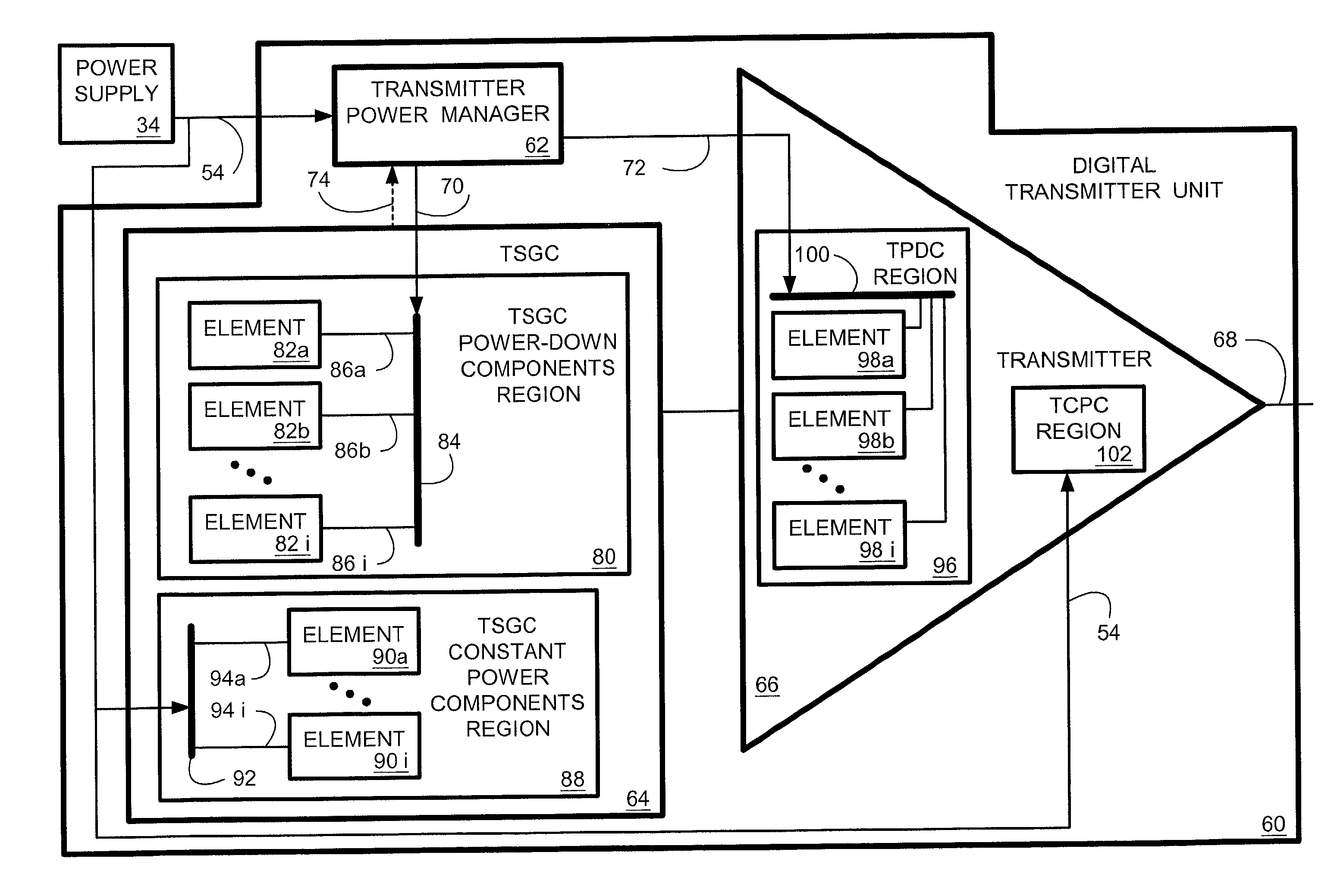
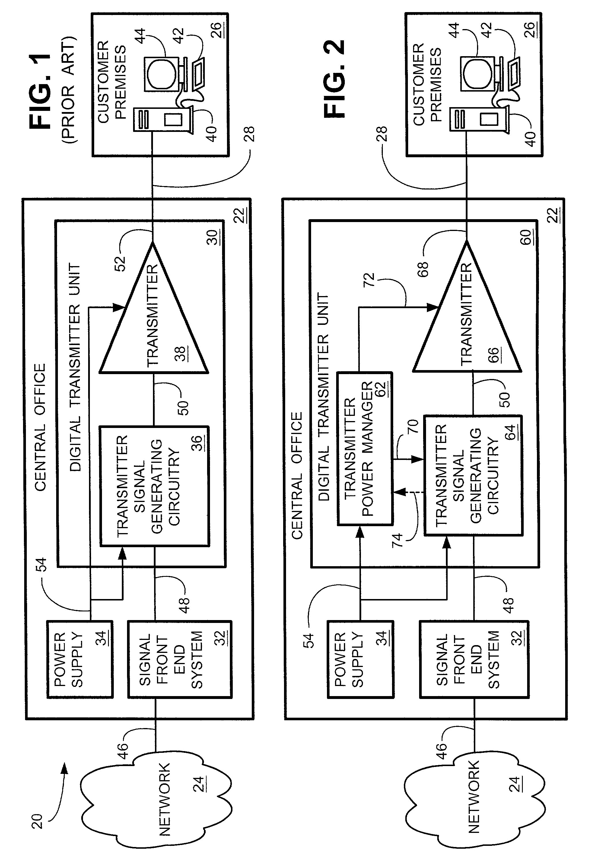
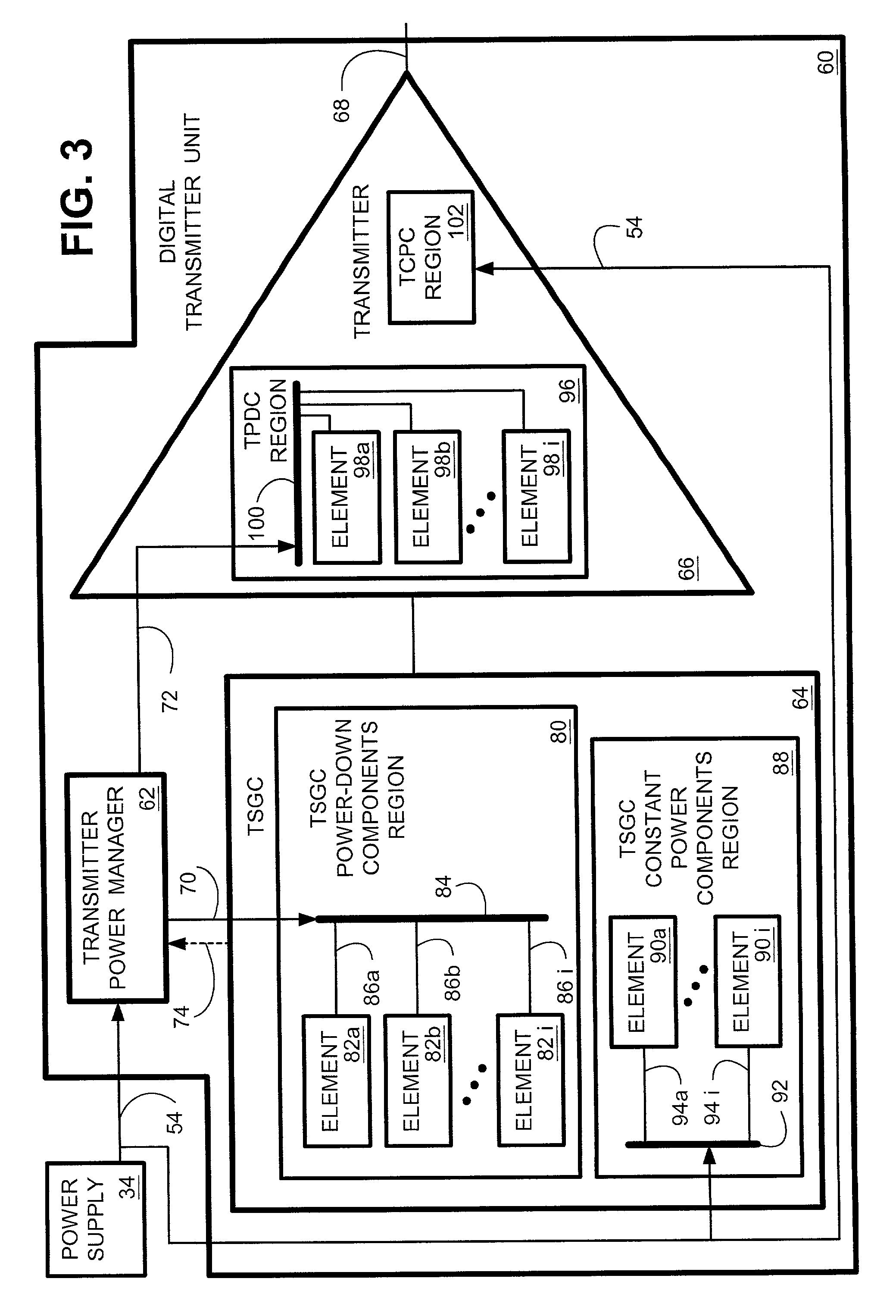
[0028]When a plurality of communication connections are coupled to a common communication device, it may be desirable to reduce power consumption in at least some of the components of the communication system. FIG. 2 is a simplified block diagram illustrating a transmitter power manager system and method of the present invention implemented in a digital transmitter unit 60. For convenience of illustration, and for convenience of explaining the operation and functionality of the present invention, the transmitter power manager system and method is discussed in the context of providing service to a single customer premises 26. Digital transmitter unit 60 is shown as coupled to subscriber loop 28, thereby providing connectivity to PC 40 residing at customer premises 26. In an actual telephony system 20, central office 22 would typically be connected to a plurality of customer premises (not shown) via a plurality of sub...


PUM


Abstract

The present invention provides for a system and method for reducing power consumption in frame and cell data transmission systems. A transmitter power manager powers down (turns off) selected elements of a transmitter system during periods of transmitter inactivity. The transmitter power manager system detects incoming communication signals which are to be transmitted by the transmitter, and at the appropriate time, powers up (turns on) the selected elements which are controlled by the transmitter power manager.

Description

CLAIM OF PRIORITY[0001]This document claims priority to and the benefit of the filing date of co-pending and commonly assigned provisional application entitled “Minimized Power Consumption For Frame And Cell Data Transmission Systems” assigned Ser. No. 60 / 176,933, filed Jan. 18, 2000, and is hereby incorporated herein by reference.TECHNICAL FIELD[0002]The present invention relates generally to data communications, and more particularly, to a system and method for managing power consumption in a transmitter and in associated signal generating circuitry.BACKGROUND OF THE INVENTION[0003]With the increasing bandwidth demands from the advent of the Internet, service providers have looked for ways to increase data transmission performance over the copper wire local loop transmission lines that connect telephone central offices (COs) to customer premises (CPs). In conventional telephony networks, customer premises equipment (CPE) are coupled to CO switches over the above mentioned transmis...

Claims


Application Information

Patent Timeline
Patent Type & Authority Patents(United States)
IPC IPC(8): G06F1/32
CPCG06F1/3203H04W52/287G06F1/3287Y02B60/1278Y02B60/1282Y02B60/50Y02D10/00
Inventor BREMER, GORDONBINGEL, THOMASCOSTON, CHUCKMARTINEZ, RAFAEL
Owner SUMMIT TECH SYST LP
Learn More