Orbital engine

a technology of orbital engine and combustion engine, which is applied in the direction of liquid fuel engine, combination engine, machine/engine, etc., can solve the problems of less economical and reduced efficiency of turbine engine, and achieve the effect of adding to the operational smoothness of the engin

Inactive Publication Date: 2006-06-13
WRIGHT INNOVATIONS
View PDF43 Cites 30 Cited by
  • Summary
  • Abstract
  • Description
  • Claims
  • Application Information

AI Technical Summary

Benefits of technology

[0010]The present invention is different from any engine known to the inventor. Unlike known engines, the present invention is not a rotary, turbine, or reciprocating engine. The engine of the present invention does have pistons, however the pistons do not travel in a straight line, like in known engines, but instead the pistons travel in a circle, and therefore do not have to stop and reverse direction, such as at the top and bottom of a stroke, allowing the engine of the present invention to operate efficiently. The orbital motion of the engine of the present invention also lends itself to higher power and smoother operation. Like a turbine engine, the circular motion of the engine of the present invention is efficient. However, unlike the engine of the present invention, a turbine engine does not have a closed volume for the force to act upon, and thus a turbine engine loses a quantity of power. To make up for this loss of power, a turbine engine must use more fuel, making it less economical.
[0013]The fuel induction system can be much like a normal reciprocating engine, with an exception of a valve train. Instead of using conventional tappet or poppet valves, the engine of the present invention uses a rotary disc valve, a reed valve, a ball valve, or the like. This allows the engine to rotate at higher revolutions per minute without having the valves float. Additionally, this adds to the operational smoothness of the engine.

Problems solved by technology

However, unlike the engine of the present invention, a turbine engine does not have a closed volume for the force to act upon, and thus a turbine engine loses a quantity of power.
To make up for this loss of power, a turbine engine must use more fuel, making it less economical.

Method used


Image

  • Orbital engine
  • Orbital engine
  • Orbital engine

Examples


Embodiment Construction

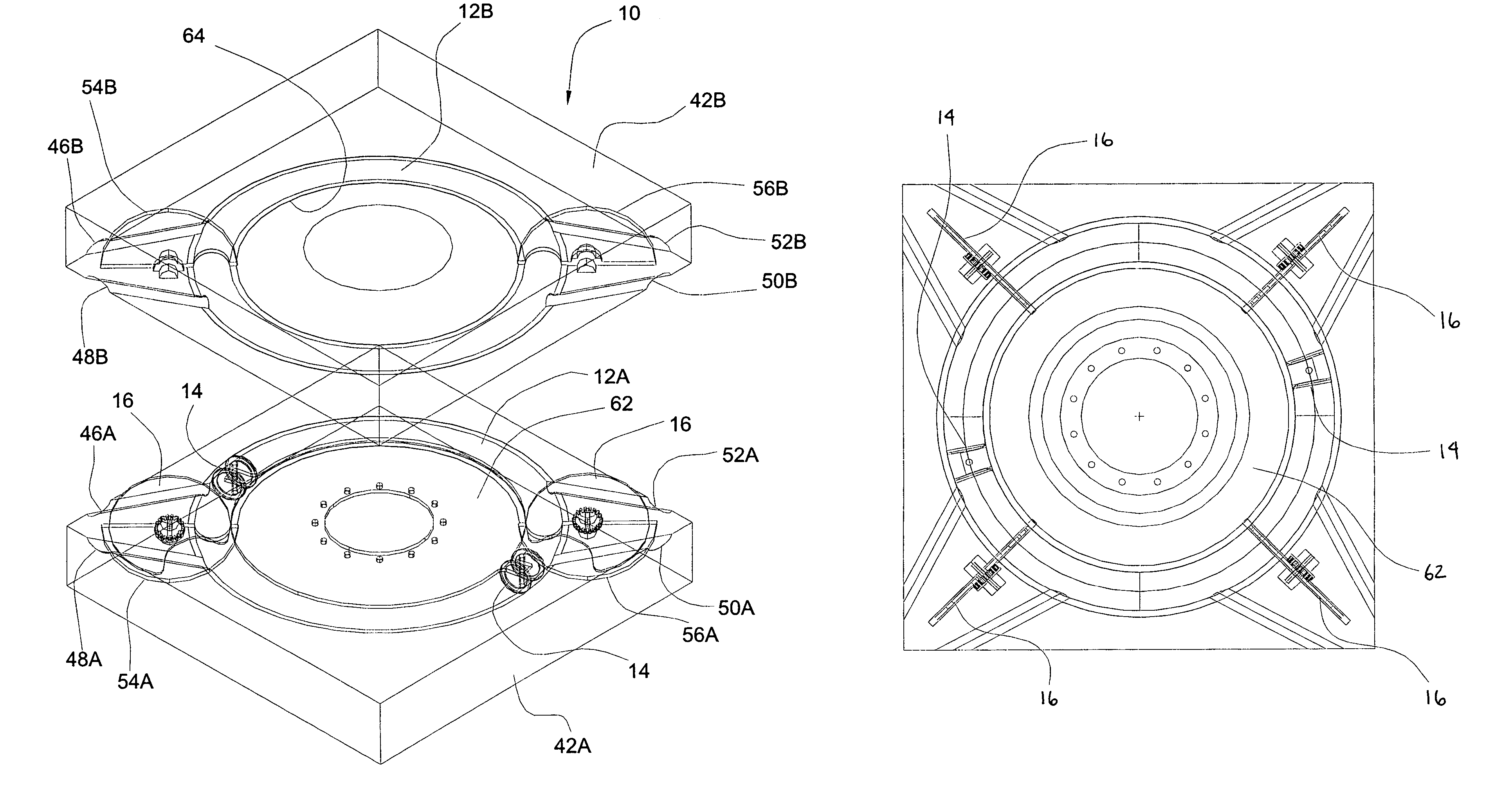
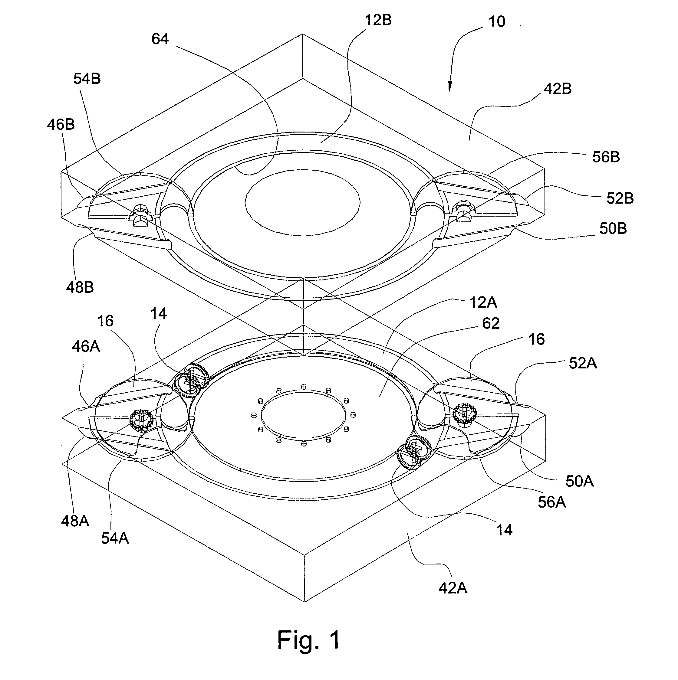
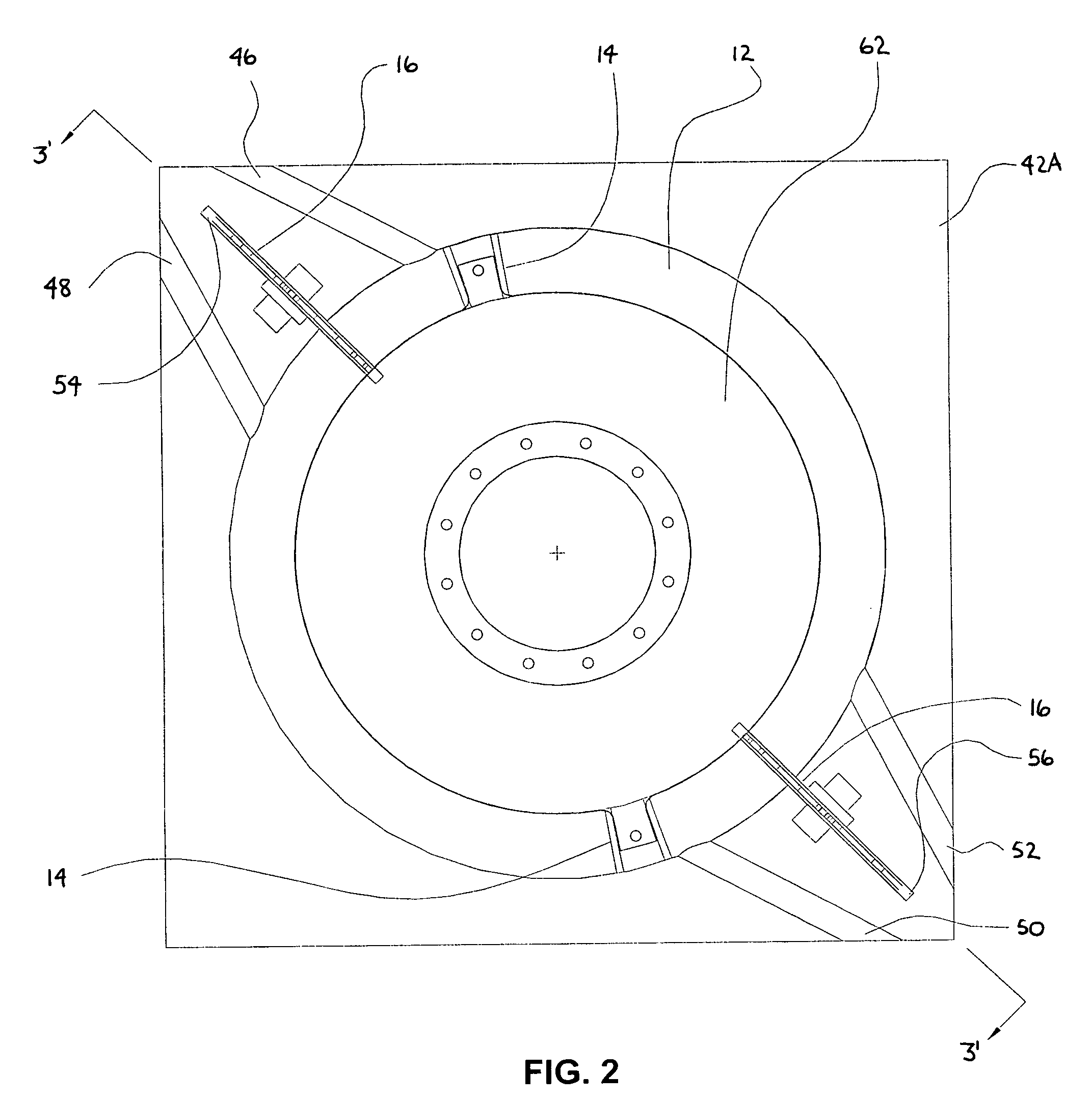
[0033]Referring now generally to FIGS. 1–15, preferred embodiments of the invention are shown. FIG. 1 is an exploded perspective view of the engine 10 of the present invention showing the two half design of the piston chamber 12. FIG. 2 is a sectional top view of a two piston 14 embodiment of the engine 10 showing the relative positioning of the various primary components of the engine 10. FIG. 3A is a sectional side view of the engine through line 3′—3′ of FIG. 2 showing the general shape of the piston chamber 12 and the positioning and operation of the chambering valves 16, which in this view are disc valves. FIG. 3B is an enlarged side view of the left side portion of FIG. 3A showing the relationship of the piston to the piston chamber and the valve cavity slot and how the connecting disc interacts with the piston chamber.

[0034]FIG. 4A is a side view of an illustrative disc valve 16 used in the engine showing a preferred single notch 80 structure. FIG. 4B is a side view of an alt...


PUM


Abstract

An engine is disclosed including at least one piston which is positioned within a toroidal piston chamber. A method of operating an engine is disclosed wherein a piston is advanced in a toroidal piston chamber past a first valve and the first valve is closed to form a first ignition chamber area located within the piston chamber between the first valve and the rear side of the piston. A second valve is closed ahead of the piston to form a first exhaust removal chamber area located within the piston chamber between the second valve and the front side of the piston, the exhaust removal chamber including exhaust gases from a preceding ignition which occurred in the first ignition chamber area. A fuel mixture is introduced into the first ignition chamber area and ignited thereby advancing the piston further along the toroidal piston chamber.

Description

BACKGROUND OF THE INVENTION[0001]1. Technical Field[0002]This invention generally relates to internal combustion engines and more specifically relates to internal combustion engines having an orbital piston movement in which the pistons move in a toroidal path.[0003]2. Prior Art[0004]Internal combustion engines generally can be categorized into three primary types: reciprocating or bore and stroke, rotary, and turbine. Each of these three types is well established and has been continuously enhanced throughout their long lineages.[0005]A reciprocating or bore and stroke engine is an internal-combustion engine in which the crankshaft is turned by pistons moving up and down in cylinders. Typically, for automotive use, a reciprocating engine is of the four-stroke variety, in which an explosive mixture is drawn into the cylinder on the first stroke and is compressed and ignited on the second stroke, work is done on the third stroke and the products of combustion are exhausted on the four...

Claims


Application Information

Patent Timeline
Patent Type & Authority Patents(United States)
IPC IPC(8): F02B53/04F01C1/00F01C1/08F01C1/30F01C3/02F01C11/00F02B53/00F02B75/00
CPCF01C3/02F01C11/002F02B2730/03F02B53/00
Inventor WRIGHT, MICHAEL D.
Owner WRIGHT INNOVATIONS
Why Eureka
Try Eureka