Fabric light control window covering

a technology of window coverings and fabric, applied in the field of fabric window coverings, can solve the problems of lack of one feature of the window covering, failure to meet the requirements of the application, so as to prevent distortion, constant and uniform pressure, and constant feed rate

Inactive Publication Date: 2006-06-13
HUNTER DOUGLAS INC
View PDF172 Cites 45 Cited by
  • Summary
  • Abstract
  • Description
  • Claims
  • Application Information

AI Technical Summary

Benefits of technology

[0020]Included in the present invention is a means for positioning the first sheer fabric in order to stop a portion for application of a cut strip and then reposition and stop the fabric before the application of the next cut strip while maintaining a constant feed rate for the first sheer fabric. This portion of the apparatus comprises two dancer rollers around which the first sheer fabric runs. The dancer rollers are mounted on shafts which form the pivot points of a linkage around its frame. The linkage causes the dancer rollers to act in concert and the timing of the rotation of the linkage is controlled by an appropriately shaped cam member.
[0021]A heat setting means is provided in which the sandwiched layers of the window covering pass between first and second adjacent endless belts. The belts each run across hot and cool surfaces to successively heat and cool the window covering. In one embodiment, the hot and cool surfaces are rollers and tension induced in the belts causes a pressure to be exerted on the sandwiched layers, thus maintaining the layers under constant and uniform pressure at a tension significantly less than the tension induced in the endless belts. In another embodiment, the hot and cool surfaces are flat plates disposed opposite air plenums and the pressure exerted on the sandwiched layers is due to the biasing of the belts toward the flat plates by pressurized air supplied to the air plenums. Alternatively, the hot and cool surfaces may be pairs of oppositely disposed flat plates biased against the belts. Heat setting in these manners allows the sandwiched layers to be set to a uniform temperature and size relationship to prevent distortions in subsequent use.

Problems solved by technology

However, window coverings of that type lack one feature which is often desired by consumers.
However, these attempts have lacked one or more of the features discussed above and have been less than successful.
A number of undesirable features of the Froget window covering derive from the fact that it is constructed utilizing a heat-welding process.
First, this limits the fabrics which may be utilized to thermoplastic materials.
Also, heat-welding necessarily requires a melting of at least some of the fibers of the materials bonded, thus providing an uneven outer appearance along the heat-welds and producing unwanted crimps or creases in the materials, which can result in fatigue failure.
Further, heat-welding is a relatively slow process which may require six or more seconds to-create a bond over an extended length.
This is too slow for application in high volume commercial production processes.
Other drawbacks of the Froget window covering are that heat welds are limited in strength, especially at elevated temperatures experienced by an insulating type shade placed adjacent a sunlit window; and the difficulty in achieving uniformly straight heat welded joints over an extended length.
Such a window covering does not provide a uniform appearance because the accordion-pleated fabric located closer to the top of the window covering does not expand to the same extent as the fabric closer to the bottom of the window covering.
Also, it is very difficult to ensure that such accordion-pleated fabric returns to its desired position after each expansion.
The construction of Cole inherently creates an undesirable feature if a woven type sheer fabric is used for the folded over, long rectangular piece of fabric.
That undesirable feature is a moire effect or interference pattern which would result when light is viewed through the folded over fabric.
The Froget window covering would also appear to have this drawback because the embodiment shown in FIG. 8 of that patent appears to show front and back fabrics of the same material.

Method used


Image

  • Fabric light control window covering
  • Fabric light control window covering
  • Fabric light control window covering

Examples


Embodiment Construction

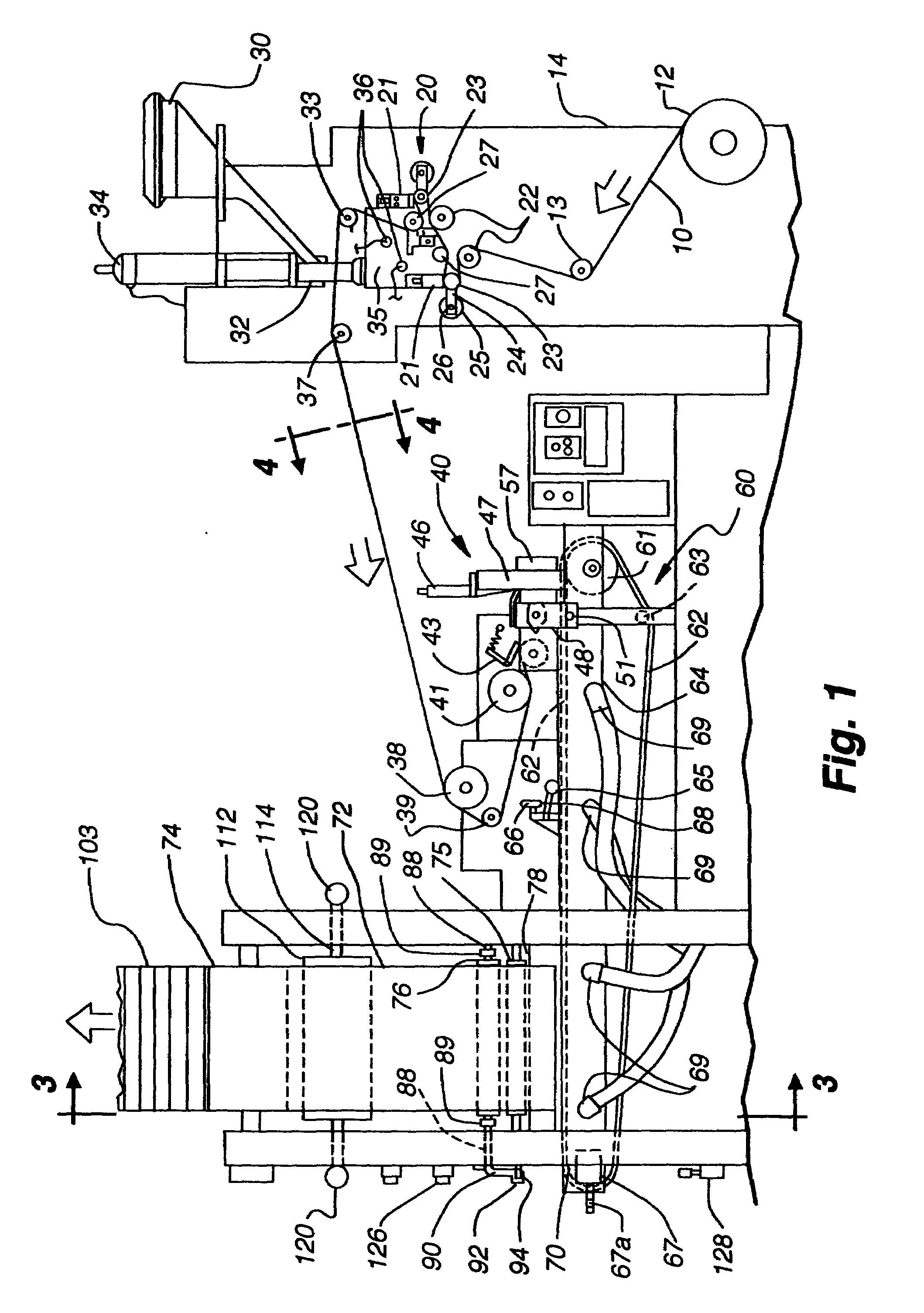
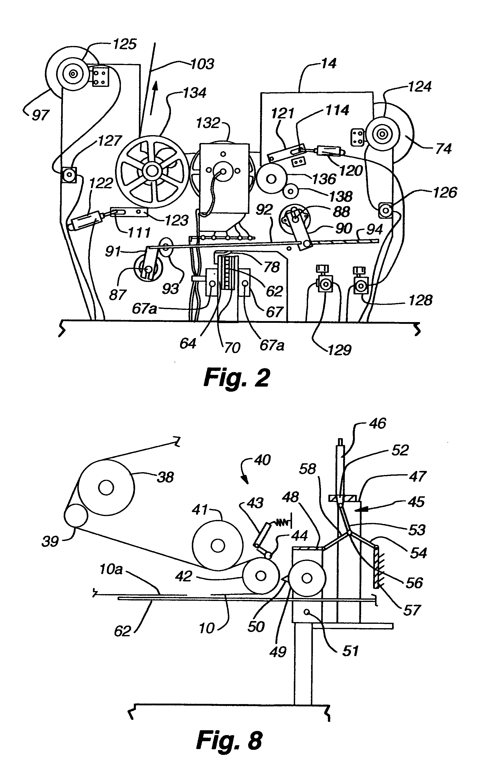
[0062]Referring to the drawing and, in particular, first to FIG. 1, the method and apparatus according to the present invention may be explained in greater detail. Vane material is provided as a continuous strip material from supply roll 12. Vane material 10 first passes around idler roller 13 mounted on frame 14. The vane material then enters adhesive applicator assembly 20, where adhesive nozzles 21 apply a thin line 16 of hot-melt adhesive to each side of the vane material 10 (see FIG. 4). While the apparatus is explained below in connection with hot-melt adhesive, it should be readily appreciated that the same principles are generally applicable to other types of liquid adhesives.

[0063]In assembly 20 vane material 10 first passes around alignment roller 22 which is provided with raised edges in order to ensure proper alignment of the material. Vane material 10 next passes around backup roller 23 over which nozzle 21 is disposed. Backup roller 23 is mounted on arm 24 and shaft 26...


PUM

PropertyMeasurementUnit
widthaaaaaaaaaa
heightaaaaaaaaaa
heightaaaaaaaaaa

Abstract

A fabric light control window covering in which fabric vanes are adhesively bonded between two sheer fabric sheets such that relative movement between the sheer fabric sheets in a direction perpendicular to the longitudinal direction of the fabric vanes changes the angle of the fabric vanes and, thus, controls the amount of light admitted through the shade. The vanes are bonded to the sheer fabric sheets in a manner which tends to bias the sheer fabric sheets together to the nonlight admitting position. Also, disclosed are methods and apparatus for manufacturing the above window covering. The method features linear application of adhesive to the vane material which provides for a uniform appearance in the finished product. A heat setting process and apparatus is disclosed in which the bonded layers of sheer fabrics and vanes are fed between belts over hot and cool surfaces, under uniform tension and pressure. This provides for heat setting of the layers of the window covering to a uniform temperature-size relationship without inducing wrinkles or distortion into the fabric during heat setting.

Description

CROSS-REFERENCE TO RELATED APPLICATIONS[0001]This application is a continuation of application Ser. No. 09 / 892,150, filed Jun. 26, 2001, abandoned, which is a continuation of application Ser. No. 09 / 608,492, filed Jun. 30, 2000, abandoned, which is a continuation of application Ser. No. 09 / 020,736, filed Feb. 9, 1998, U.S. Pat. No. 6,112,797, which is a continuation of application Ser. No. 08 / 485,051, filed Jun. 7, 1995, U.S. Pat. No. 5,718,799, which is a division of application Ser. No. 08 / 243,000, filed May 16, 1994, U.S. Pat. No. 6,001,199, which is a continuation of application Ser. No. 07 / 867,476, filed Apr. 13, 1992, abandoned, which is a division of application Ser. No. 07 / 701,165, filed May 17, 1991, U.S. Pat. No. 5,313,999, which is a continuation-in-part of application Ser. No. 07 / 602,998, filed Oct. 24, 1990, abandoned. Each of the above-identified patent applications or patents is hereby incorporated by reference as if fully disclosed herein.BACKGROUND OF THE INVENTION[...

Claims


Application Information

Patent Timeline
Patent Type & Authority Patents(United States)
IPC IPC(8): E06B9/08A47H23/08A47H23/00B29C65/00B29C65/02E06B9/24E06B9/26E06B9/266E06B9/34G11C29/00
CPCB29C65/02B29C66/83433B29C66/43B29C66/437E06B9/24E06B9/26E06B9/262E06B9/266G11C29/789G11C29/83B29C66/1122B29C66/83423B29C66/729B29C65/7847B29C65/00B29L2031/7192E06B2009/2435E06B2009/2627Y10S160/07B29C65/10B29C65/18B29C66/71B29C66/8161B29C66/8266B29C66/8322B29C66/91421B29C66/91431B29C66/91645B29C66/919B29K2067/00
Inventor COLSON, WENDELL B.SWISZCZ, PAUL G.
Owner HUNTER DOUGLAS INC
Why Eureka
Try Eureka