Two-hop telemetry interface for medical device

a telemetry interface and medical device technology, applied in the field of medical systems, devices, methods, can solve the problems of poor spatially-coordinated heart contraction of patients, diminished blood circulation, and reduced blood circulation

Inactive Publication Date: 2006-06-13
CARDIAC PACEMAKERS INC
View PDF90 Cites 169 Cited by
  • Summary
  • Abstract
  • Description
  • Claims
  • Application Information

AI Technical Summary

Benefits of technology

[0008]In one example, this document discusses an external telemetry interface device to assist in communication between an implantable medical device carrying an inductive element and an external remote first far-field radio-frequency (RF) transceiver. The telemetry interface device includes an inductive transceiver, configured to be communicatively coupled to the inductive element in the implantable medical device via a mutual inductance therebetween. It also includes a second far-field RF transceiver, configured to be communicatively coupled to the remote first far-field RF transceiver. It further includes a data buffer, coupled to the inductive and second far-field RF transceivers, to store data from the inductive and second far-field RF transceivers. Moreover, the telemetry interface device includes a controller, coupled to the inductive and second far-field RF transceivers and the data buffer, to issue control signals directing communication by the inductive and second far-field RF transceivers using data from the data buffer.
[0009]In another example, this docume...

Problems solved by technology

Moreover, some patients have poorly spatially-coordinated heart contractions.
In either case, diminished blood circulation may result.
Such too-fast heart rhythms also cause diminished blood circulation because the heart isn't allowed sufficient time to fill with blood before contracting to expel the blood.
Such pumping by the heart is inefficient.
One problem faced by cardiac rhythm management devices and other implantable medical ...

Method used


Image

  • Two-hop telemetry interface for medical device
  • Two-hop telemetry interface for medical device
  • Two-hop telemetry interface for medical device

Examples


Embodiment Construction

[0019]In the following detailed description, reference is made to the accompanying drawings which form a part hereof, and in which is shown by way of illustration specific embodiments in which the invention may be practiced. These embodiments are described in sufficient detail to enable those skilled in the art to practice the invention, and it is to be understood that the embodiments may be combined, or that other embodiments may be utilized and that structural, logical and electrical changes may be made without departing from the spirit and scope of the present invention. The following detailed description is, therefore, not to be taken in a limiting sense, and the scope of the present invention is defined by the appended claims and their equivalents.

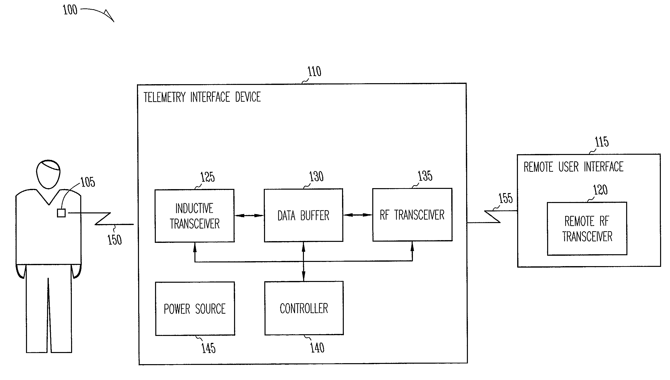
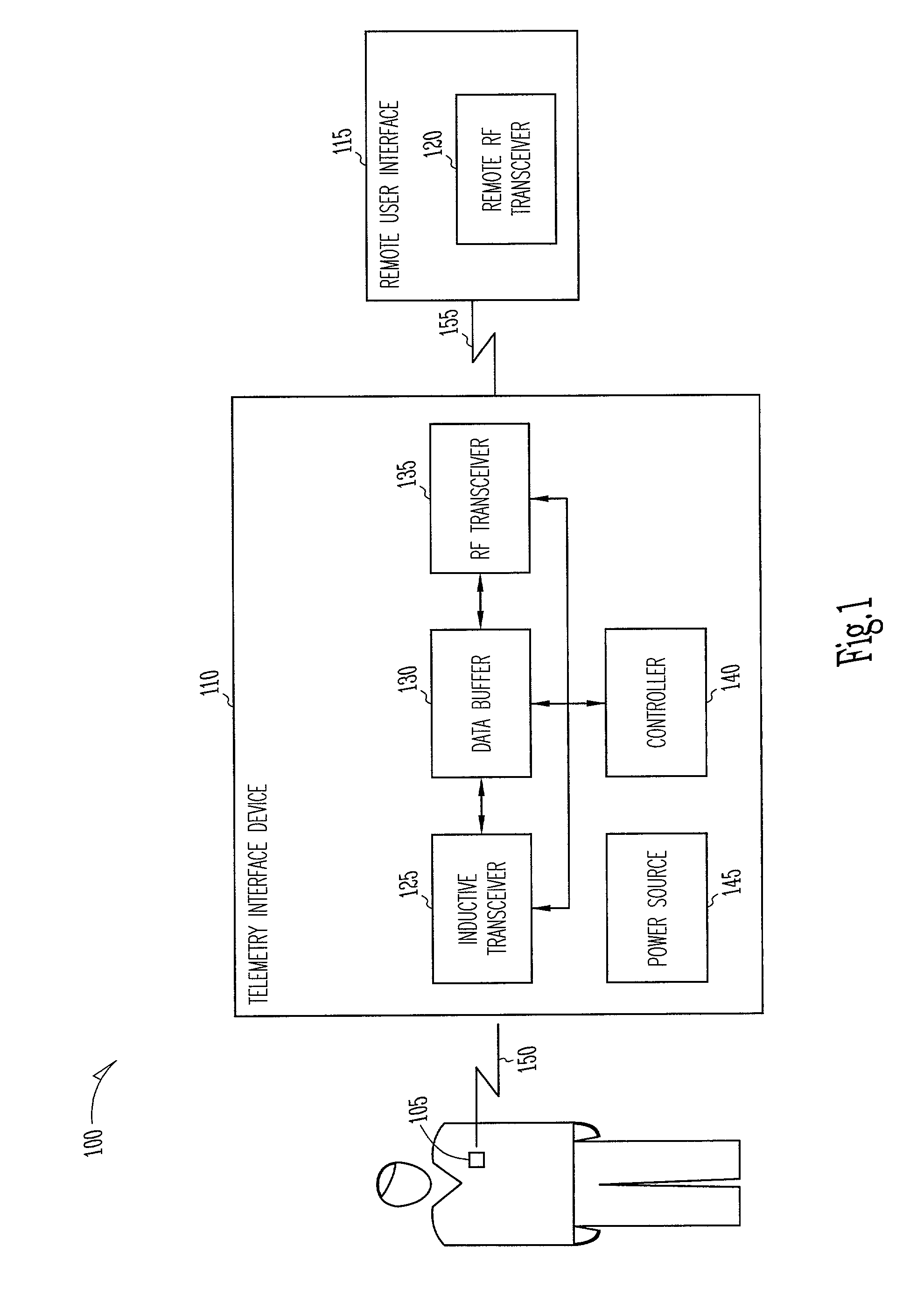
[0020]FIG. 1 is a block diagram illustrating generally portions of a system 100 including an implantable medical device 105 (such as a cardiac rhythm management device), an external telemetry interface (I / F) device 110, and a remote u...


PUM


Abstract

This document discusses a system that includes an intermediary telemetry interface device for communicating between a cardiac rhythm management system or other implantable medical device and a programmer or other remote device. One example provides an inductive near-field communication link between the telemetry interface and the implantable medical device, and a radio-frequency (RF) far-field communication link between the telemetry interface device and the remote device. The telemetry interface device provides data buffering. In another example, the telemetry interface device includes a data processing module for compressing and/or decompressing data, or for extracting information from data. Such information extraction may include obtaining heart rate, interval, and/or depolarization morphology information from an electrogram signal received from the implantable medical device.

Description

TECHNICAL FIELD[0001]This document relates generally to medical systems, devices, and methods, and particularly, but not by way of limitation, to a two-hop telemetry interface for a medical device such as an implantable cardiac rhythm management device.BACKGROUND[0002]When functioning properly, the human heart maintains its own intrinsic rhythm. Its sinoatrial node generates intrinsic electrical cardiac signals that depolarize the atria, causing atrial heart contractions. Its atrioventricular node then passes the intrinsic cardiac signal to depolarize the ventricles, causing ventricular heart contractions. These intrinsic cardiac signals can be sensed on a surface electrocardiogram (ECG) obtained from electrodes placed on the patient's skin, or from electrodes implanted within the patient's body. The surface ECG waveform, for example, includes artifacts associated with atrial depolarizations (“P-waves”) and those associated with ventricular depolarizations (“QRS complexes”).[0003]A ...

Claims


Application Information

Patent Timeline
IPC IPC(8): A61B5/00A61N1/08
CPCA61N1/08G08C2201/40A61N1/37223A61N1/37282
Inventor VON ARX, JEFFREY A.LYDEN, MICHAEL J.LINDER, WILLIAM J.MAZAR, SCOTT T.KOSHIOL, ALLAN T.GRYZWA, MARKNAUMAN, DOROTHYHOSTINE, SCOTT
Owner CARDIAC PACEMAKERS INC
Why Eureka
Try Eureka