Wind power plant

a wind power plant and wind turbine technology, applied in the direction of electric generator control, machines/engines, mechanical equipment, etc., can solve the problems of fire hazards, reduced system efficiency, and increased cost of transformers, and achieve the effect of low stray losses

Inactive Publication Date: 2006-06-13
ABB (SCHWEIZ) AG
View PDF751 Cites 54 Cited by
  • Summary
  • Abstract
  • Description
  • Claims
  • Application Information

AI Technical Summary

Benefits of technology

[0031]The use of a cable of the type described above allows the entire length of the outer sheath of the winding, as well as other parts of the plant, to be kept at earth potential. An important advantage is that the electric field is close to zero within the coil-end region outside the outer semiconducting layer. With earth potential on the outer sheath the electric field need not be controlled. This means that no field concentrations will occur either in the core, in the coil-end regions or in the transition between them.
[0032]The mixture of insulated and / or uninsulated impacted strands, or transposed strands, results in low stray losses. The cable for high voltage used in the magnetic circuit winding is constructed of an inner core / conductor with a plurality of strands, at least two semiconducting layers, the innermost being surrounded by an insulating layer, which is in turn surrounded by an outer semiconducting layer having an outer diameter in the order of 10-40 mm and a conductor area in the order of 10-200 mm2.

Problems solved by technology

The transformers entail an extra cost and also have the drawback that the total efficiency of the system is reduced.
They are also a fire hazard since they contain transformer oil which can leak out in the event of failure or vandalism.
Furthermore today's stator winding insulation technology is sensitive to temperature variations, humidity and salt that a wind turbine generator may be exposed to.
This makes it unrealistic with today's technology to dispose of the distribution transformers.
If there are more than two layers these crossings complicate the winding work and the coil end is less satisfactory.
However, the machine designs according to the above publications do not permit optimal utilization of the electromagnetic material in the stator.
Another drawback is that the line-commutated inverter consumes reactive power.

Method used


Image

  • Wind power plant
  • Wind power plant
  • Wind power plant

Examples


Embodiment Construction

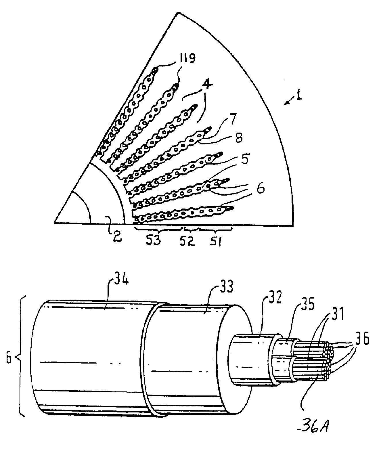
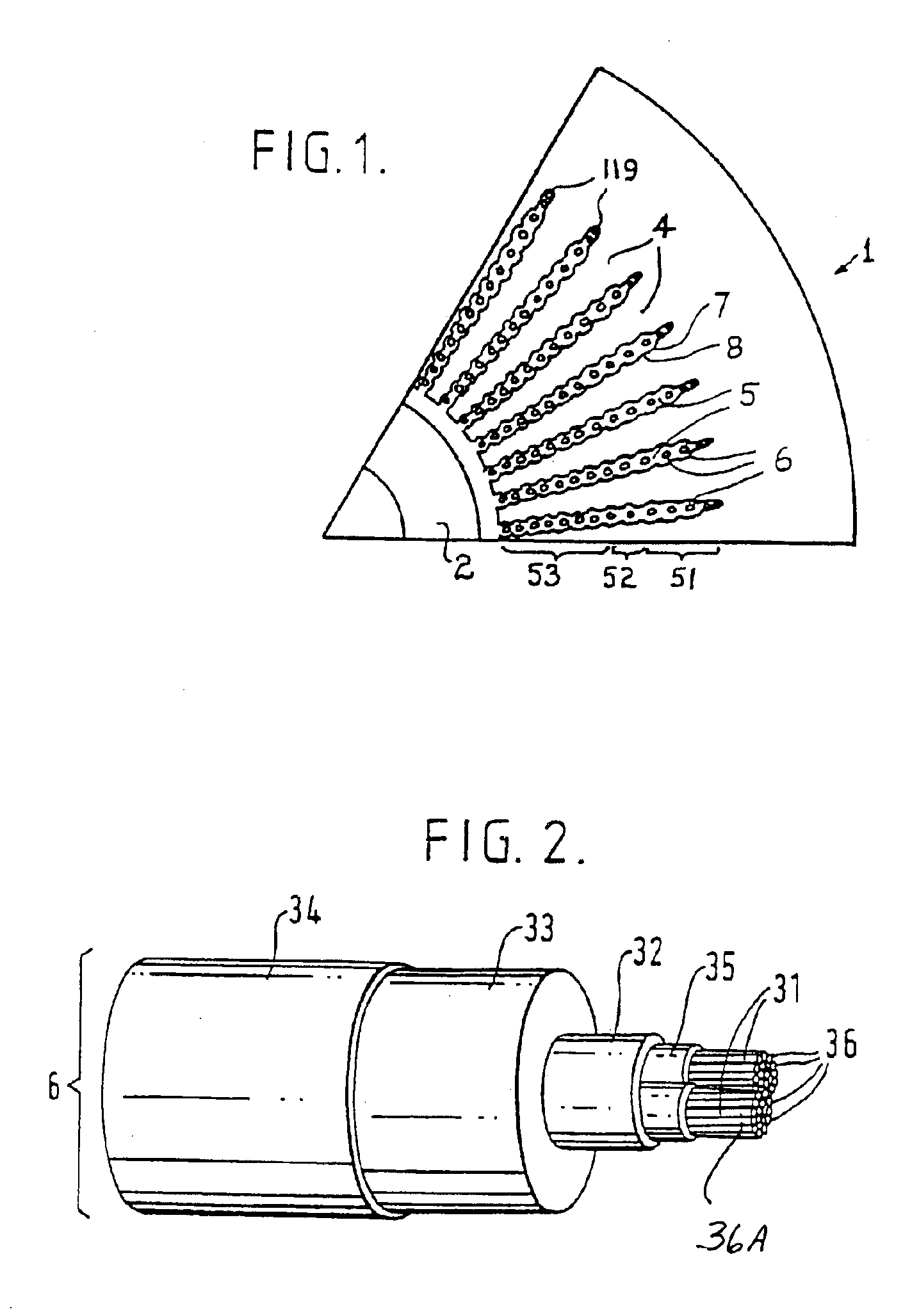
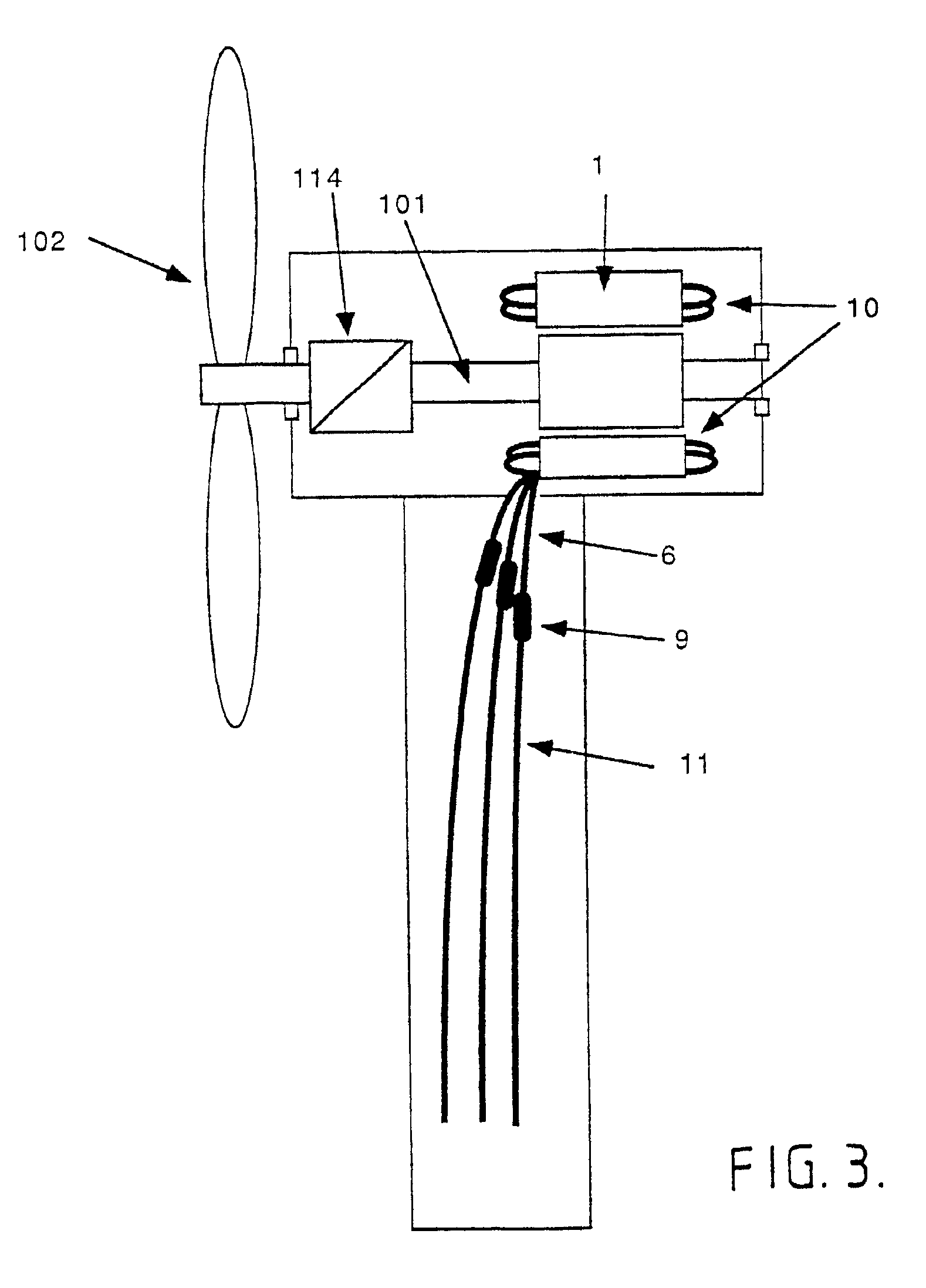
[0011]The object of the invention is thus to provide an electric generator which can be used in a wind power plant for such high voltage that the distribution transformer can be omitted, i.e. a plant in which the electric generators are intended for considerably higher voltages than conventional machines of corresponding type, in order to be able to execute direct connection to power networks at all types of high voltages, in particular exceeding the 20 kV considered as an upper limit today. Another object of the invention is to provide an electric generator that is not sensitive to salt, humidity or temperature variations, as are present known high-voltage windings. A third object of the invention is to provide a variable speed alternative for the resulting high voltage if the distribution transformer is eliminated.

[0012]By use of solid insulation in combination with the other features defined, the network can be supplied without the use of an intermediate step-up transformer even ...


PUM


Abstract

The magnetic circuit of a generator in a wind power plant is arranged to directly supply a high supply voltage of 2-50 kV, preferably higher than 10 kV. The generator is provided with solid insulation and its winding includes a cable (6) comprising one or more current-carrying conductors (31) with a number of strands (36) surrounded by at least one outer and one inner semiconducting layer (34, 32) and intermediate insulating layers (33). The outer semiconducting layer (34) is at earth potential. The stator winding may be produced with full or fractional slot winding, the phases of the winding being Y-connected. The Y-point may be insulated and protected from over-voltage by means of surge arrestors, or else the Y-point may be earthed via a suppression filter. The invention also relates to a wind power plant, a generator included in the plant and a variable speed system for such a plant.

Description

TECHNICAL FIELD[0001]This invention relates to a wind power plant which is intended for connection to distribution or transmission networks, hereinafrer called power networks. The invention also relates to an electric generator for high voltage in a wind power station intended for the above-mentioned purpose. The invention further relates to a variable speed system containing the above-mentioned generator.BACKGROUND ART[0002]A wind power plant can be a single grid-connected unit but usually consists of a number of wind turbines forming a wind power farm. Each wind turbine is equipped with an electric generator located in a hub. The generator can be synchronous or of the induction type. Induction generators are more common today because they are cheaper and more robust. The synchronous generator can produce reactive power which is an advantage over the induction machine. The size of the wind turbine is today typically 100-3000 kW with many commercial turbines around 500 kw. The trend...

Claims


Application Information

Patent Timeline
Patent Type & Authority Patents(United States)
IPC IPC(8): F03D9/00H02K3/40F03D11/02H02K21/14
CPCF03D9/002F03D11/02H02K3/40H02K2203/15Y10S174/28Y02E10/725H02K7/1838Y10S174/15Y02E10/722F03D15/00F03D9/25Y02E10/72
Inventor LEIJON, MATSKYLANDER, GUNNAR
Owner ABB (SCHWEIZ) AG
Why Eureka
Try Eureka