Ultrasonic transducer and ultrasonic flowmeter

Inactive Publication Date: 2006-06-13
PANASONIC CORP
View PDF13 Cites 76 Cited by
  • Summary
  • Abstract
  • Description
  • Claims
  • Application Information

AI Technical Summary

Benefits of technology

[0085]Another ultrasonic transducer according to the present invention includes a piezoelectric body having a principal surface that transmits and/or receives an ultrasonic wave and an acoustic matching member provided on the principal surface of the piezoelectric body. The acousti

Problems solved by technology

In the ultrasonic flowmeter shown in FIG. 35, if the alternating current voltage is applied to one of the ultrasonic transducers continuously, then the ultrasonic transducer radiates an ultrasonic wave continuously, thereby making it difficult to measure the propagation time.
However, it is very difficult to find such a substance in solid materials.
However, the acoustic impedance of each of these materials is greater than 50×104 kg/m2/s and cannot be regarded as satisfying Equation (5).
However, a material such as a dry gel with very low acoustic impedance normally has a low mechanical strength.
In particularly, the dry gel is relatively strong with respect to a stress applied in the compressing direction but is extremely weak to a stress applied

Method used


Image

  • Ultrasonic transducer and ultrasonic flowmeter
  • Ultrasonic transducer and ultrasonic flowmeter
  • Ultrasonic transducer and ultrasonic flowmeter

Examples


embodiment 1

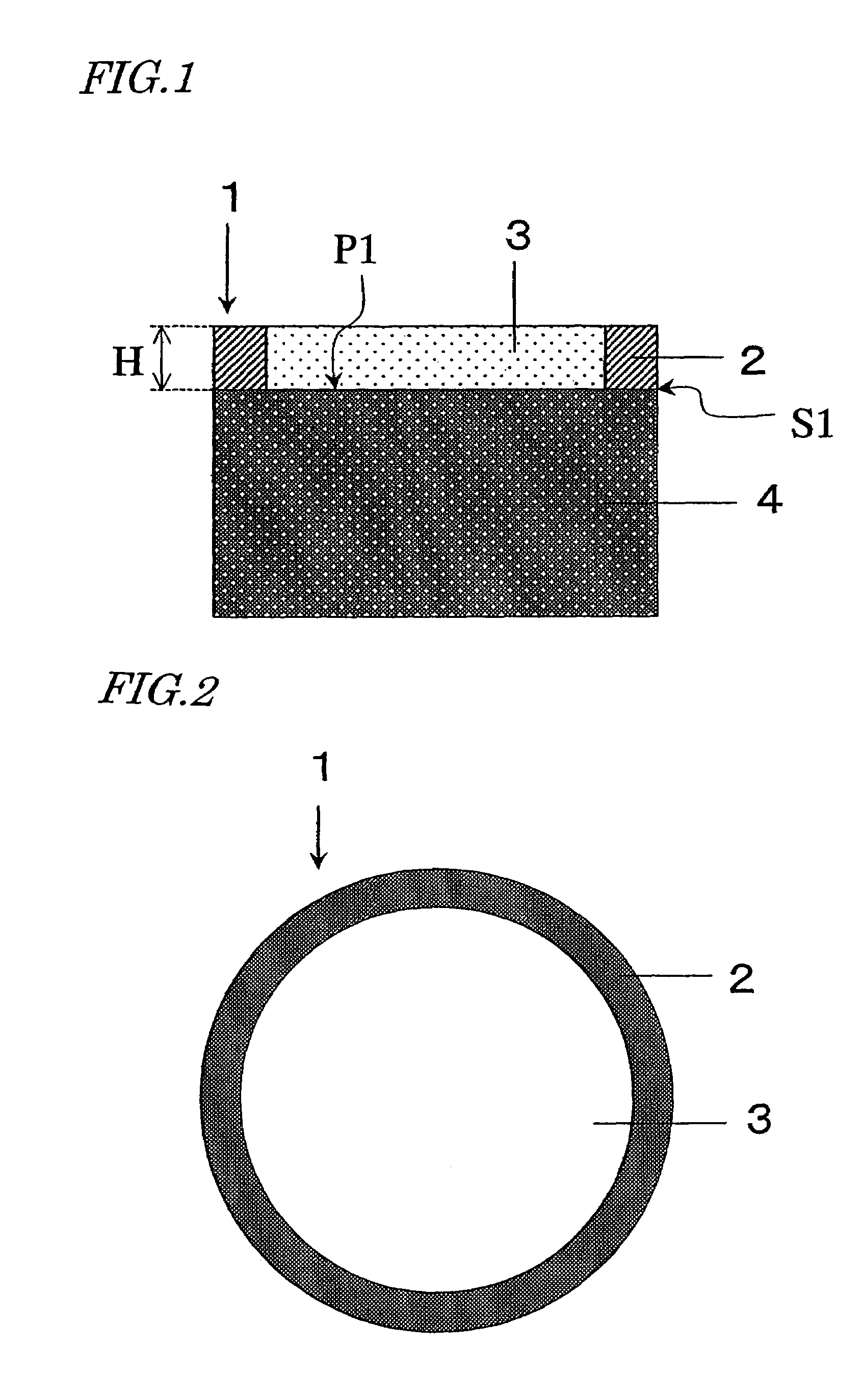
[0126]FIG. 1 shows a cross section of an ultrasonic transducer (or ultrasonic oscillator) according to a first embodiment of the present invention. The ultrasonic transducer 1 shown in FIG. 1 includes a piezoelectric body 4, an acoustic matching layer 3 provided on the piezoelectric body 4, and a protective portion 2 secured to the piezoelectric body 4.

[0127]The piezoelectric body 4 is made of a material with piezoelectricity, and is polarized in the thickness direction thereof. The upper and lower surfaces of the piezoelectric body 4 are provided with electrodes (not shown), and the piezoelectric body 4 radiates an ultrasonic wave in response to signals applied to those electrodes. On receiving an ultrasonic wave on the other hand, the piezoelectric body 4 generates a voltage signal between the electrodes. According to the present invention, the piezoelectric body 4 may be made of any known material.

[0128]The height H of the protective portion 2 as measured from the principal surfa...

embodiment 2

[0165]Hereinafter, a second embodiment of the present invention will be described with reference to FIG. 5.

[0166]In this preferred embodiment, the protective portion and the piezoelectric body are combined together. Specifically, a concave portion 5a is defined at the center of the principal surface of the piezoelectric body 5 such that a portion of the piezoelectric body 5 may be used as the protective portion. In other words, the portion 5b of the piezoelectric body 5 functions as the protective portion and the protective portion and the piezoelectric body are combined together.

[0167]The ultrasonic transducer shown in FIG. 5 may be fabricated in the following manner.

[0168]First, a piezoelectric body 5 that has already been subjected to a polarization process is provided, and has one of its principal surfaces patterned into the concave portion 5a. The patterning process to define the concave portion 5a may be carried out by an end mill or a sandblast. The depth of the concave porti...

embodiment 3

[0173]Hereinafter, a third embodiment of the present invention will be described with reference to FIG. 8.

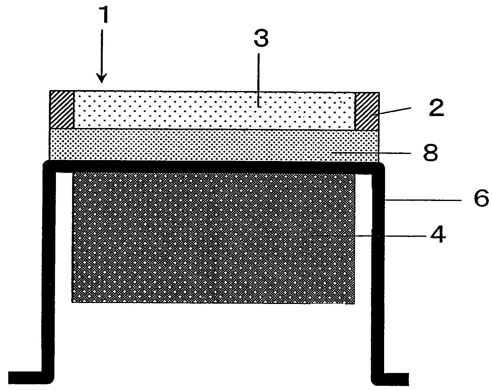
[0174]This embodiment is characterized by including a structure supporting member 6. The structure supporting member 6 shown in FIG. 8 includes a disklike supporting portion 6a, on which the acoustic matching layer 3 and so on are fixed, and a cylindrical portion 6b that extends continuously from the disklike supporting portion in the axial direction. The end of the cylindrical portion has an L-cross section such that the structure supporting member 6 can be easily secured to a shielding plate 60 or another apparatus.

[0175]The acoustic matching layer 3 and the protective portion 2 are arranged on the surface of the supporting portion 6a of the structure supporting member 6, while the piezoelectric body 4 is provided on the back surface of the supporting portion 6a. That is to say, the piezoelectric body 4 and the acoustic matching layer 3 are provided so as to face each other wi...


PUM


Abstract

An ultrasonic transducer according to the present invention includes: a piezoelectric body 4 to set up ultrasonic vibrations; an acoustic matching layer 3 made of a material with a density of 50 kg/m3 to 1,000 kg/m3 and an acoustic impedance of 2.5×10³ kg/m2/s to 1.0×10⁶ kg/m2/s; a lower acoustic matching layer 9 provided between the piezoelectric body 4 and the acoustic matching layer 3; and a structure supporting member 6 that supports the lower acoustic matching layer 9 and the piezoelectric body 4 thereon and shields the piezoelectric body 4 from a fluid that propagates the ultrasonic vibrations. The ultrasonic transducer includes a protective portion, which contacts with at least a portion of a side surface of the acoustic matching layer 4. This protective portion is defined by a portion of the lower acoustic matching layer 9 and forms an integral part of the lower acoustic matching layer 9.

Description

CROSS-REFERENCE TO RELATED APPLICATION[0001]This application is a Section 371 of International Application No. PCT / JP03 / 00742, filed Jan. 27, 2003, the disclosure of which is incorporated herein by reference.TECHNICAL FIELD[0002]The present invention relates to an ultrasonic transducer having an acoustic matching layer and a method for fabricating such a transducer, and also relates to an ultrasonic flowmeter including such an ultrasonic transducer.BACKGROUND ART[0003]In recent years, an ultrasonic flowmeter has been used as a gas meter, for example. The ultrasonic flowmeter measures the time that it takes for an ultrasonic wave to go a predetermined distance within a tube in which a fluid is flowing, and calculates the flow velocity of the fluid, thereby obtaining its flow rate based on the flow velocity.[0004]FIG. 35 illustrates a cross-sectional structure for a main portion of an ultrasonic flowmeter of that type. The ultrasonic flowmeter is arranged such that a fluid under measu...

Claims


Application Information

Patent Timeline
IPC IPC(8): H01L41/08G01F1/66G10K11/02
CPCG10K11/02G01F1/662
Inventor NAGAHARA, HIDETOMOHASHIMOTO, MASAHIKOSUZUKI, MASAAKIHASHIMOTO, KAZUHIKOHASHIDA, TAKASHISHIRAISHI, SEIGOTAKAHARA, NORIHISA
Owner PANASONIC CORP
Why Eureka
Try Eureka