Optical fiber transmission system, raman gain slope measuring device and raman gain slope measuring method

a technology of optical fiber transmission system and raman gain, which is applied in the direction of optical apparatus testing, transmission monitoring, instruments, etc., can solve the problems of difficult to predict in advance the pump power required to obtain the desired raman gain, no simple actual method for making such measurements at site, and labor and time-consuming. , to achieve the effect of excellent workability and cost performan

Inactive Publication Date: 2006-06-13
NEC CORP
View PDF18 Cites 19 Cited by
  • Summary
  • Abstract
  • Description
  • Claims
  • Application Information

AI Technical Summary

Benefits of technology

[0018]An object of the present invention is to provide an optical fiber transmission system, a Raman gain slope measuring device and a Raman gain slope measuring method enabling Raman gain slope measurement which is excellent in workability and cost performance and which can be realized by work at one end of a transmission line and requires no change of wiring at the signal transmission state.

Problems solved by technology

Thus, when distributed Raman amplification is conducted on an existing transmission line whose parameters affecting gain vary widely, it is difficult to predict in advance the pump power required for obtaining a desired Raman gain.
Adjustment at the site is therefore needed which costs labor and time.
As described above, while actual measurement of Raman gain slope is crucial, there exists no simple actual method for making such measurements at site.
It, however, has a problem in that the method is not easy to perform because the opposite ends of a transmission line are apart from each other in general.
The embodiment of FIG. 7, however, requires a special and expensive OTDR device to be provided at a DRA installation site.
The method also requires a temporary change of the transmission line wiring for connecting the OTDR device, which invites problems in costs and workability.
On the other hand, although such a conventional method as shown in FIG. 7 enables measurement of Raman gain slope even when work is possible only at one end of a transmission line, it requires an expensive OTDR device to be provided at the site and also transmission line wiring to be changed for connecting the OTDR device, leaving problems to be solved in costs and workability.

Method used


Image

  • Optical fiber transmission system, raman gain slope measuring device and raman gain slope measuring method
  • Optical fiber transmission system, raman gain slope measuring device and raman gain slope measuring method
  • Optical fiber transmission system, raman gain slope measuring device and raman gain slope measuring method

Examples


Embodiment Construction

[0088]The preferred embodiment of the present invention will be discussed hereinafter in detail with reference to the accompanying drawings. In the following description, numerous specific details are set forth in order to provide a thorough understanding of the present invention. It will be obvious, however, to those skilled in the art that the present invention may be practiced without these specific details. In other instance, well-known structures are not shown in detail in order to unnecessary obscure the present invention.

[0089]First, principle of the present invention will be described.

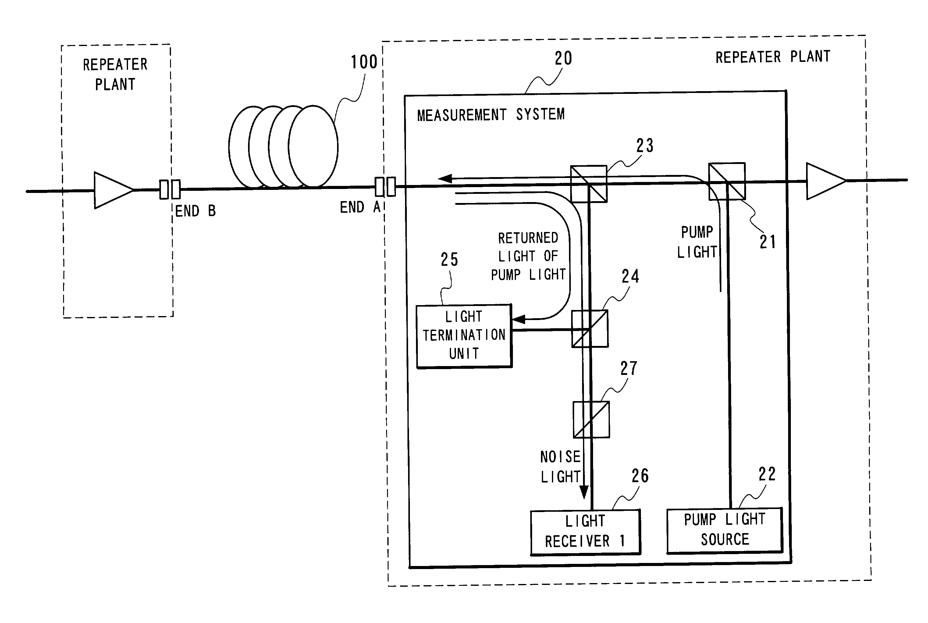
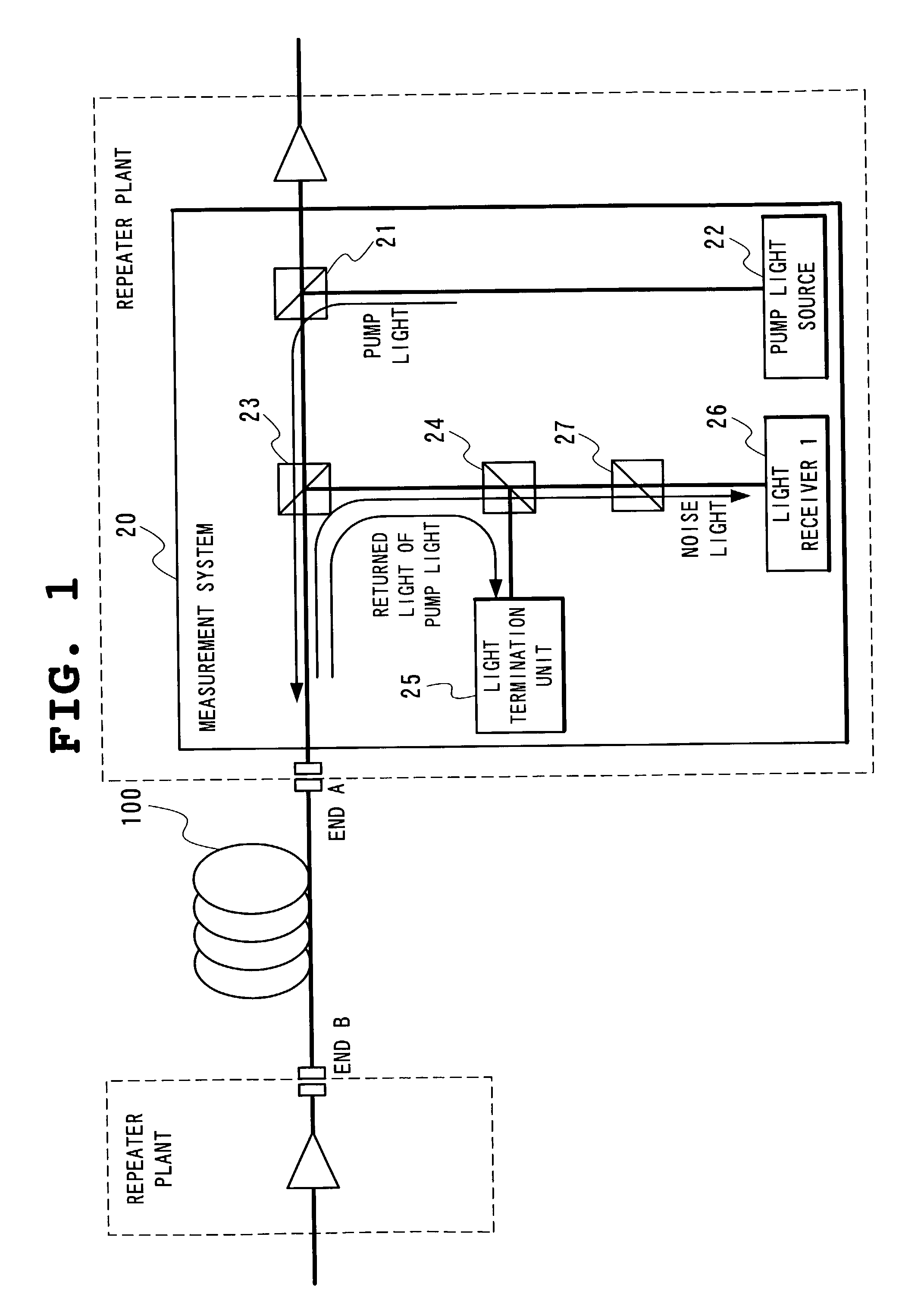
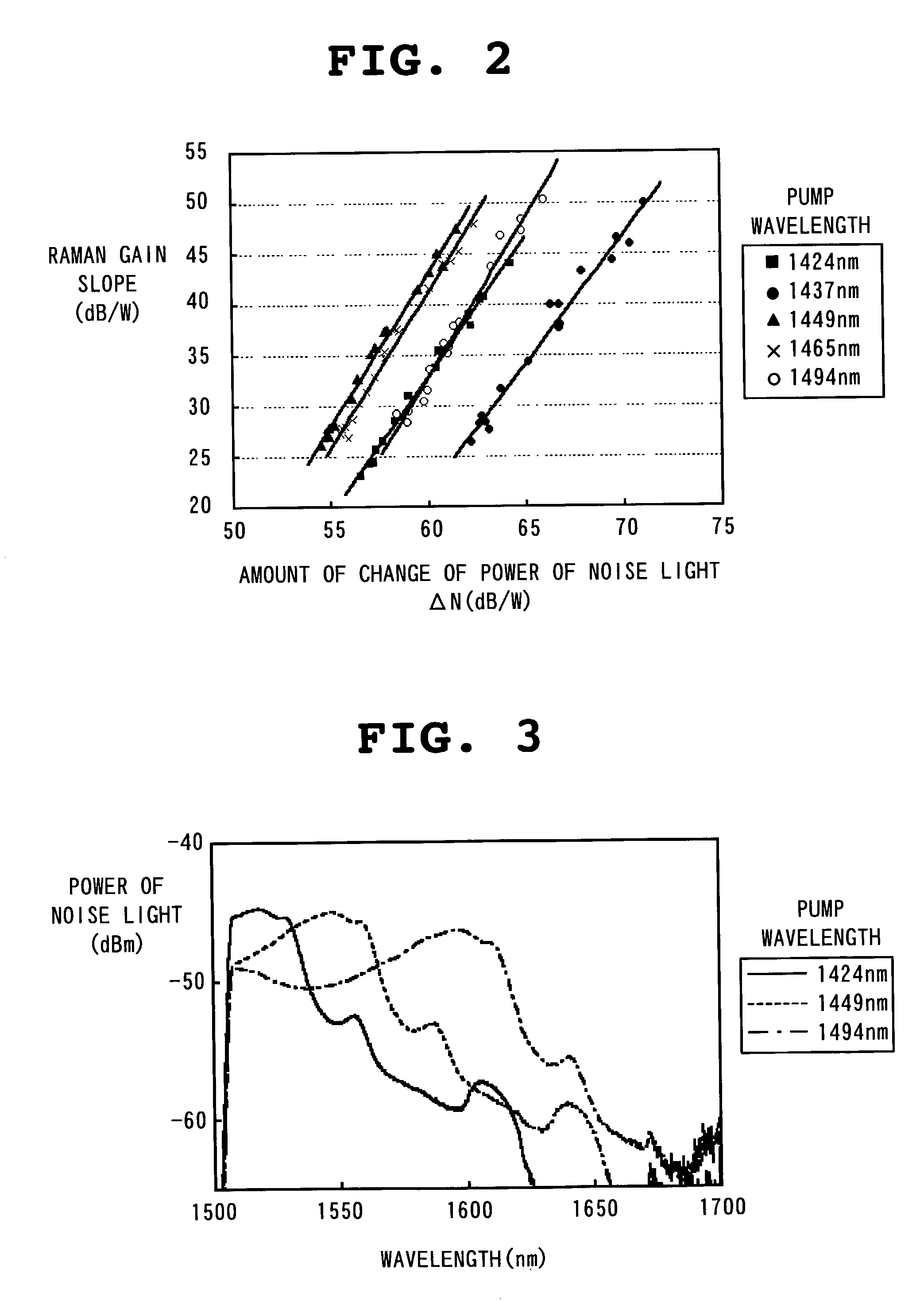
[0090]When pump light for Raman amplification is made incident on a transmission line, noise light according to an amount of a Raman gain is generated. Reversely calculating a Raman gain from a measurement value of power of the noise light is the essential feature of the present invention. Components of noise light are mainly composed of amplified spontaneous Raman scattering derived from Raman...


PUM

PropertyMeasurementUnit
wavelengthaaaaaaaaaa
wavelengthsaaaaaaaaaa

Abstract

In Raman gain slope measurement method and device measures Raman gain slope which is a value obtained by normalizing a gain generated by Raman amplification caused by pump light incident on an optical fiber by optical power of the pump light in question. The method and device measures the power of noise light and operates based on a relationship between the optical power of pump light incident on an optical fiber and the optical power of the measured noise light generated by the application of the pump light, Raman gain slope of the optical fiber in question is thus calculated.

Description

BACKGROUND OF THE INVENTION[0001]1. Field of the Invention[0002]The present invention relates to an optical fiber transmission system, a Raman gain slope measuring device and a Raman gain slope measuring method which enable measurement of Raman gain slope of an optical fiber transmission line.[0003]2. Description of the Related Art(Distributed Raman Amplification)[0004]In the field of communication systems using an optical fiber transmission line, development is under way for commercializing distributed Raman amplification (DRA) techniques. Optical fiber for use in basic transmission networks today employs quartz glass as a base material. Raman amplification is a phenomenon that takes place when a signal light and a pump light having a frequency 13 THz higher than that of the signal light are simultaneously incident on a quartz glass causing part of energy of the pump light to be transferred to the signal light through the induced Raman scattering effect of the quartz glass. As a re...

Claims


Application Information

Patent Timeline
Patent Type & Authority Patents(United States)
IPC IPC(8): H04B10/12H04B10/08G01M11/02G01M11/00G02F1/35H01S3/00H01S3/30H04B10/00H04B10/071H04B10/2537H04B10/291
CPCG01M11/319H01S3/0014H01S3/302
Inventor SOBE, MASAAKIYANO, YUTAKA
Owner NEC CORP
Why Eureka
Try Eureka