Adaptive multi-channel, multi-function

a multi-functional, adaptive technology, applied in the field of adaptive multi-channel, multi-function, can solve the problems of difficult to differentiate and sort out intercepted radar signals using coarse conventional parameters alone, drastic reduction of peak transmitted power, and ambiguity in sorting, classification and identification processes, etc., to achieve good compromise between performance and cost, reduce hardware and total system cost, and improve the effect of cost and component utilization

Inactive Publication Date: 2006-06-13
HER MAJESTY THE QUEEN AS REPRESENTED BY THE
View PDF6 Cites 3 Cited by
  • Summary
  • Abstract
  • Description
  • Claims
  • Application Information

AI Technical Summary

Benefits of technology

[0050]It is an advantage of the present invention that the number of receiving channels is kept to a minimum resulting in a reduction of hardware and total system cost. In an embodiment of the invention, four parallel receiving channels have been used. Four channels were selected as this number of channels provides a good compromise between performance and cost. For example, most multi-port components and devices are designed with outputs that are multiples of two. As such, a choice of four channels has a positive impact on cost and component utilization. Having selected the number of parallel channels as four, these four channels are inputs to the four-channel down-converter 250 and ADCs 290. The architecture 200 is designed to make use of these four channels to perform, adaptively, all of the basic functions required by a receiving system as outlined above.
[0051]Switching Matrix. In order to transform a large number (M) of antenna outputs (e.g. 28) to a small number (N) of receiving channels (e.g. 4), the switching matrix 260 is used to map the M antenna outputs 321 into the N receiving channels. The switching matrix 260 performs a spatial distribution mapping of antenna outputs 321 into four parallel receiving channels. Referring to FIG. 3, there is shown a block diagram illustrating a spatial mapping 300 of antenna outputs 321 from a four-face antenna array block 210, where each face 211, 212, 213, 214 has seven antenna elements 221, into four parallel receiving channels 310, 320, 330, 340 in accordance with an embodiment of the invention. This spatial mapping 300 may be performed using 8-pole-single-throw (“8PST”) switches. Various other spatial mappings may also be used depending on the antenna array pattern 220, 230, 240 and the number of faces 211, 212, 213, 214 to be covered.
[0052]Typically, one of the antenna outputs 321 from each antenna face 211, 212, 213, 214 is mapped onto one of the four parallel channels 310, 320, 330, 340 of a four-channel down-converter 250 for detecting the presence of signals from all four directions. Consequently, all of the signals from any direction within the down-converted frequency band may be detected and characterized.
[0053]A coarse AOA may also be determined by using a method of amplitude comparison. Once the direction of a signal of interest is located within a quadrant (e.g. 211), the switching matrix 260 can be re-configured. Any four outputs 321 of the antenna arrays 223, 224 in that particular face 211 can then be routed to the four-channel down-converter 250 to accurately determine the corresponding azimuth and elevation angles. This may be accomplished by sequentially measuring these angles or through a combination of other methods. For example, in the case of the second antenna array pattern 230 shown in FIG. 2, both the azimuth and elevation angles may be measured simultaneously.
[0054]Since high-speed and high-performance ADCs for EW applications are not typically available, while lower-cost COTS components are now readily available, the receiver architecture 200 makes use of COTS components for achieving system performance requirements. Commercial ADCs with an 8-bit resolution, sampling at a 1-GHz rate, are presently available from suppliers including Thomson-CSF, Maxim Integrated Products, and Acqiris Data Conversion Instruments. Advantageously, these COTS components may be used as basic building blocks for the receiver architecture 200. The receiver architecture 200 is based on a four-channel down-converter 250 with its output signals being digitized by 1-GHz sampling rate ADCs 290 with 8-bit resolution. The four-channel outputs 310, 320, 330, 340 of the switching matrix 260 are input to the four-channel down-converter 250. The outputs from the four ADCs 290 are input to the data processing system 270. The use of relatively low-cost COTS ADCs running at relatively modest rates may be configured to achieve extended instantaneous frequency coverage and instantaneous dynamic range. As will be described below, the present invention provides switching and processing methods to achieve improved instantaneous frequency coverage and instantaneous dynamic range while at the same time providing cancellation of unwanted and interfering signals.
[0055]Extension of Instantaneous Frequency Coverage. In order to improve the POI for searching unknown signals, the total instantaneous frequency coverage must be expanded. In the general case where the total input frequency coverage (e.g. 2–18 GHz) of the receiver 200 is much wider than the instantaneous frequency coverage (e.g. 1 GHz), a two-stage frequency conversion process is required for the down-converter 250 in order to eliminate image signals generated by the frequency conversion process. The incoming signals received by the four channels 310, 320, 330, 340 are first converted to a relatively high 1st IF signal using a common LO 280 by using either an up or down conversion process. The 1st IF signal is then down converted to the final IF signal 501, 502, 503, 504 with the same bandwidth before being digitized by an ADC 290. If all of the four parallel receiving channels 310, 320, 330, 340 are used to cover the same input frequency band, as is the case for normal operation, then the total instantaneous frequency coverage will be limited by the sampling rate of the ADCs 290. However, if each of the four channels 310, 320, 330, 340 is used to cover a slightly different input frequency band, then a much broader instantaneous frequency coverage can be achieved using the same type of ADC.

Problems solved by technology

With the proliferation of radar systems and the increasing number of radars employing complex waveform modulation, it is difficult to differentiate and sort out intercepted radar signals using coarse conventional parameters alone.
Since many radars have similar conventional parameters, when signals having similar characteristics are compared using these coarse conventional parameters, ambiguity may occur in the sorting, classification, and identification processes.
This technique can result in drastic reductions in the peak transmitted power while maintaining the required average power.
There are disadvantages with these receiver systems in that the use of different receiver technologies results in a more complex and costly system architecture and related implementation.
If correlation is not performed precisely, errors may occur in the signal recognition process.
Furthermore, the original signal content from each antenna is usually not preserved during the detection process as not all of the input data is in digital format.
While the receiver architecture proposed by Lee and using digital processing technology is ideal for performing a multi-function role, current digital receivers are still limited in the instantaneous dynamic range and bandwidth that they can achieve due to the relatively poor performance of currently available high sampling rate ADCs.
In fact, there is a considerable gap between military requirements and the current state-of-the-shelf technology.
Moreover, there are several fundamental factors that may limit the achievable dynamic range at high sampling rates (see Larson).
Consequently, even if higher sampling rates can be achieved, ADC devices are expected to be expensive and bulky.
Furthermore, with present architectures, if overall system performance is to be improved, a large number of parallel and expensive receiver channels will typically be required which will result in high implementation costs.

Method used


Image

  • Adaptive multi-channel, multi-function
  • Adaptive multi-channel, multi-function
  • Adaptive multi-channel, multi-function

Examples


Embodiment Construction

[0043]In the following description, numerous specific details are set forth to provide a thorough understanding of the invention. However, it is understood that the invention may be practiced without these specific details. In other instances, well-known software, circuits, structures and techniques have not been described or shown in detail in order not to obscure the invention. The term “data processing system” is used herein to refer to any machine for processing data, including the computer systems and network arrangements described herein. In the drawings, like numerals refer to like structures or processes.

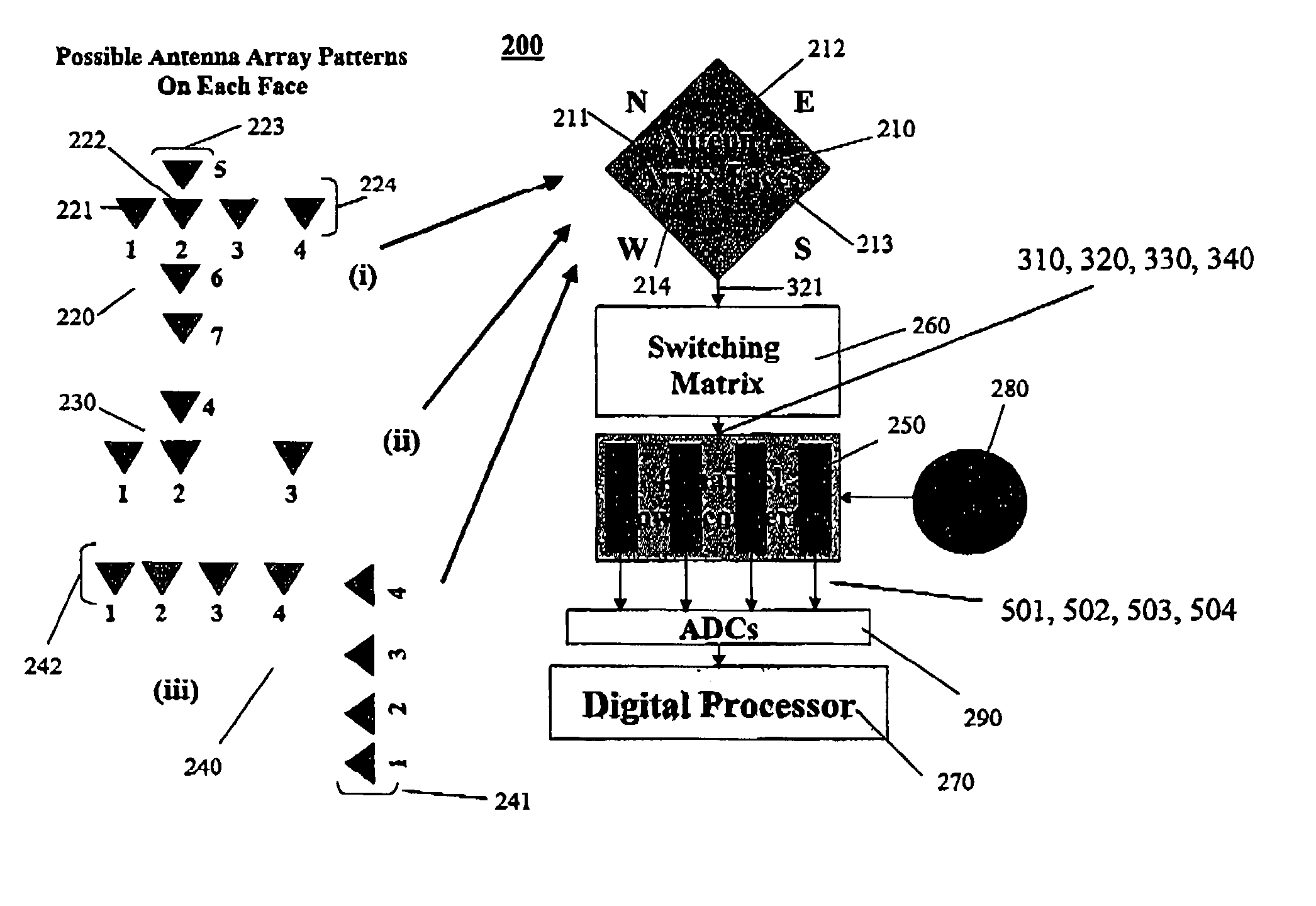
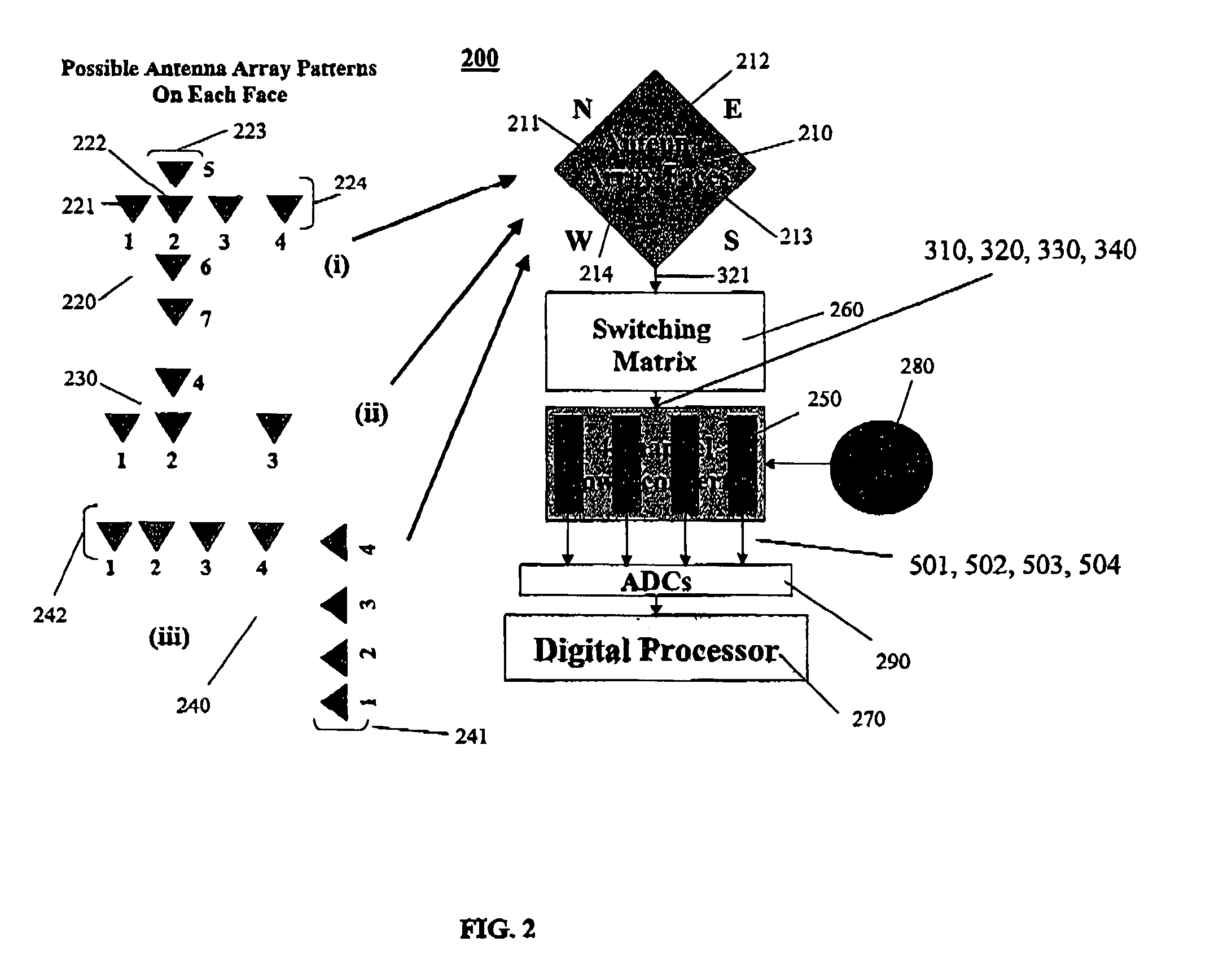
[0044]In general, the invention described herein provides a four-channel adaptive architecture for multi-function digital intercept receivers. The adaptive architecture performs the three basic functions typically required of modern intercept receivers, namely, it can be used to: (a) precisely measure and characterize conventional pulsed radar signals; (b) detect and charact...


PUM


Abstract

An adaptive receiver for determining parameters of an incoming signal is provided. The adaptive receiver includes: a) a plurality of antenna channels; each of the antenna channels including a respective antenna element for receiving the incoming signal and for outputting a respective antenna channel signal; b) a switching matrix operatively coupled to receive antenna channel signals from the antenna channels; the switching matrix for distributing the antenna channel signals to a plurality of receiver channels according to a predetermined mapping; c) a multi-channel down-converter operatively coupled to receive the antenna channel signals from the receiver channels; the multi-channel down-converter for processing the antenna channel signals to output respective intermediate frequency signals; d) a plurality of analog-to-digital converters (ADCs) operatively coupled to receive the intermediate frequency signals from the multi-channel down-converter; the ADCs for converting the intermediate frequency signals to digital signals; the digital signals being indicative of at least the phase and amplitude of the incoming signal; and, e) a digital processor operatively coupled to receive the digital signals from the ADCs for determining the parameters.

Description

[0001]This application claims priority from U.S. patent application Ser. No. 60 / 315,948, filed Aug. 31, 2001, and incorporated herein by reference.[0002]The invention relates to the field of digital intercept receivers, and more specifically to multi-channel, multi-function digital intercept receivers for military reconnaissance systems.BACKGROUND OF THE INVENTION[0003]Various reconnaissance systems are used to intercept radar signals and to decipher their characteristics and angle-of-arrival (“AOA”). For example, a microwave intercept receiver may be used for this purpose. In Electronic Warfare (“EW”) related reconnaissance applications, the receiver is typically designed to fulfil roles including radar warning, electronic support measures (“ESM”), and Electronic Intelligence (“ELINT”). (For a related discussion, see J. B. Y. Tsui, Microwave Receivers With Electronic Warfare Applications, Wiley, New York, 1986, which is incorporated herein by reference.) In most conventional approa...

Claims


Application Information

Patent Timeline
Patent Type & Authority Patents(United States)
IPC IPC(8): H04B7/10H04B1/69G01S7/285G01S13/02H04B1/18H04B7/08H04L1/02
CPCH04L1/02H04B7/0817
Inventor LEE, JIM P. Y.
Owner HER MAJESTY THE QUEEN AS REPRESENTED BY THE
Why Eureka
Try Eureka