Method of forming an embedded read element

a technology of embedded read elements and read elements, which is applied in the field of forming embedded read elements, can solve the problems of affecting affecting the stability so as to ensure the viability of embedded read elements, prevent esd damage, and maintain the resistance of embedded read elements constant

Inactive Publication Date: 2006-06-20
HITACHI GLOBAL STORAGE TECH NETHERLANDS BV
View PDF4 Cites 11 Cited by
  • Summary
  • Abstract
  • Description
  • Claims
  • Application Information

AI Technical Summary

Benefits of technology

[0012]There are several advantages provided by this method. First, the ESD damage can be prevented during the mechanical lapping, since the in-line lapping guide acts as a shunt in the parallel circuit of the embedded read element and the in-line lapping guide, and when the in-line lapping guide is completely removed, the trench act as a buffer to maintain the resistance of the embedded read element constant. The viability of the embedded read element can thus be ensured. Second, the sensor height, defined by the photolithographical patterning as opposed to the mechanical lapping, can be maintained constant during the mechanical lapping. A precise manufacturing control can thus be ensured. Third, the magnetic moments of the sense, reference and keeper layers can be maintained, while the pinning layer will not corrode, since the embedded read element is not exposed to the chemical solution and air at all. A higher signal sensitivity can thus be attained. Fourth, the ABS of the embedded read element remains smooth and doesn't require any protection overcoat. The concern on contacts with the rotating magnetic disk can thus be alleviated. Because of these advantages, the embedded read element formed in this method is suitable for magnetic recording at ultrahigh densities.

Problems solved by technology

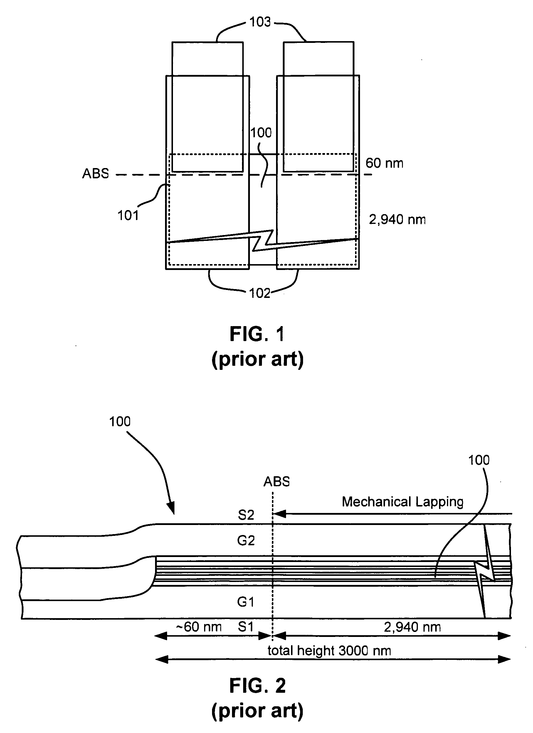
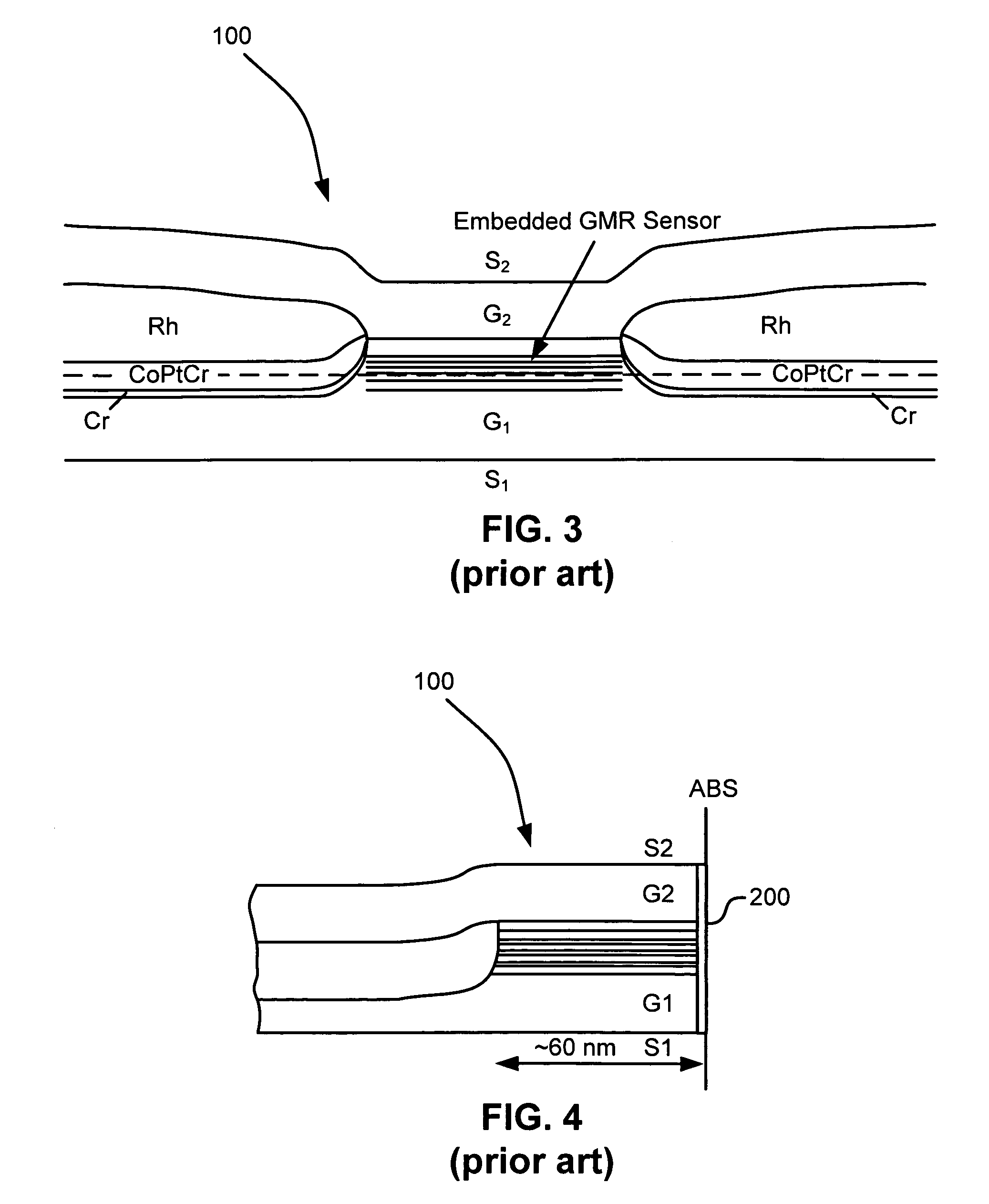
There are several disadvantages in the GMR sensor formed in the prior art.
First, electrostatic discharge (ESD) damages may occur during the mechanical lapping due to an unwanted substantial increase in the resistance of the GMR sensor 100.
The GMR sensor 100 may thus be not viable at all.
Second, the sensor height may substantially vary due to difficulties in remotely controlling the resistance of the GMR sensor 100 within a desired narrow resistance range.
A manufacturing control for a high yield may thus be very challenging.
Third, the magnetic moments of sense, reference and keeper layers at the ABS may substantially decrease by uncertain amounts, while the pinning layer may corrode, due to the exposure of the ABS to the chemical solution and air.
The designed magnetic moments and desired exchange-coupling may not be attained at the ABS, thus substantially reducing the signal sensitivity of the GMR sensor 100.
Fourth, all the various layers of the GMR sensor 100 may be recessed differently and an unwanted stepped ABS is formed, due to their different mechanical lapping rates.
The protection overcoat 200 may thus not adhere well on this stepped ABS, thus causing concerns on the contact of the GMR sensor 100 with the rotating magnetic disk during sensor operation.
Because of these problems, the GMR sensors 100 formed in the prior art may not be suitable for magnetic recording at ultrahigh densities.

Method used


Image

  • Method of forming an embedded read element
  • Method of forming an embedded read element
  • Method of forming an embedded read element

Examples


Embodiment Construction

[0028]The following description is the best embodiment presently contemplated for carrying out this invention. This description is made for the purpose of illustrating the general principles of this invention and is not meant to limit the inventive concepts claimed herein.

[0029]Referring now to FIG. 6, there is shown a disk drive 600 embodying this invention. As shown in FIG. 6, at least one rotatable magnetic disk 612 is supported on a spindle 614 and rotated by a disk drive motor 618. The magnetic recording on each disk is in the form of an annular pattern of concentric data tracks (not shown) on the magnetic disk 612.

[0030]At least one slider 613 is positioned near the magnetic disk 612, each slider 613 supporting one or more magnetic head assemblies 621. As the magnetic disk rotates, slider 613 is moved radially in and out over the disk surface 622 so that the magnetic head assembly 621 may access different tracks of the magnetic disk where desired data are written. Each slider ...


PUM

PropertyMeasurementUnit
heightaaaaaaaaaa
heightaaaaaaaaaa
resistanceaaaaaaaaaa

Abstract

A method of forming an embedded read element is used in the fabrication process of a magnetic head assembly including write and read heads. In this method, three photolithographic patterning steps are applied for defining the designed height of the embedded read element, defining its designed width, and connecting it with conducting layers, respectively. An in-line lapping guide is also formed with a spacing in front of the embedded read element. In this method, two mechanical lapping steps are applied, one monitored by measuring the resistance of a parallel circuit of the embedded read element and the in-line lapping guide, and the other monitored by measuring the GMR response of the embedded read element.

Description

FIELD OF THE INVENTION[0001]The present invention relates to a method of forming an embedded read element such as an embedded current-perpendicular-to-plane (CPP) giant magnetoresistance (GMR) sensor, a current-in-plane (CIP) GMR sensor, or a tunneling magnetoresistance (TMR) sensor.BACKGROUND OF THE INVENTION[0002]The heart of a computer is a magnetic disk drive that includes a magnetic disk, a slider where a magnetic head assembly including write and read heads is mounted, a suspension arm, and an actuator arm. When the magnetic disk is stationary, the slider is biased by the suspension arm into contact with the surface of the magnetic disk. When the magnetic disk rotates, the rotating magnetic disk swirls air at an air bearing surface (ABS) of the slider, causing the slider to fly on an air bearing. When the slider flies on the air bearing, the actuator arm swings the suspension arm to place the magnetic head assembly over selected circular tracks on the rotating magnetic disk, w...

Claims


Application Information

Patent Timeline
Patent Type & Authority Patents(United States)
IPC IPC(8): G11B5/187H01F7/06B24B37/04B24B49/10G11B5/39
CPCB24B37/013B24B49/10G11B5/39Y10T29/49041Y10T29/49048Y10T29/49046
Inventor DING, MENGHO, KUOK SANLIN, TSANNTZENG, HUEY-MING
Owner HITACHI GLOBAL STORAGE TECH NETHERLANDS BV
Why Eureka
Try Eureka