
Electrostatic vibration device

Inactive Publication Date: 2006-06-20
DENSO CORP
View PDF6 Cites 10 Cited by
  • Summary
  • Abstract
  • Description
  • Claims
  • Application Information

AI Technical Summary

Benefits of technology

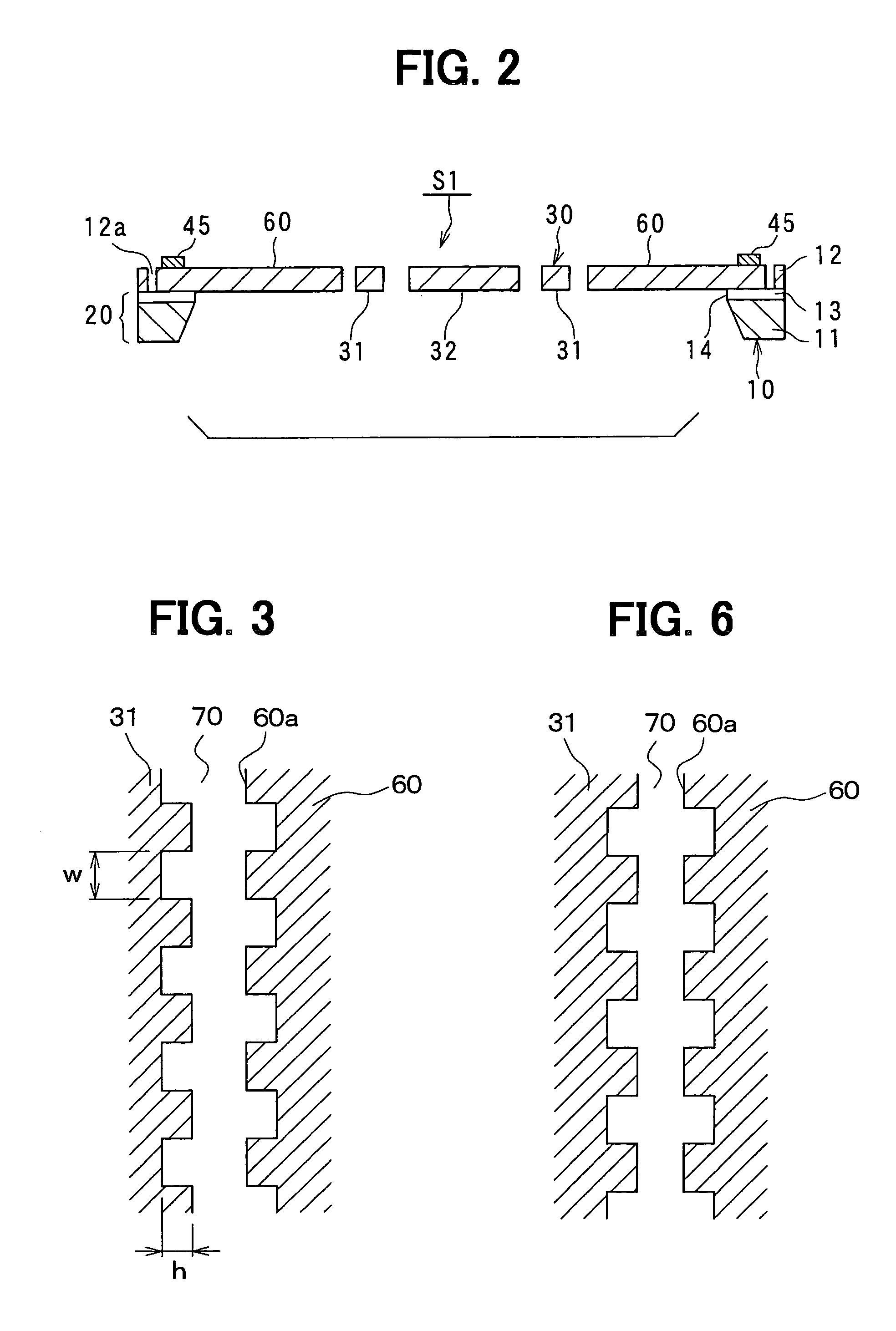
[0024]Therefore, as a result of the inventor's enthusiastic studies, it has been discovered that the faces confronting through the confronting back-side gap are designed in an evenness shape in order to reduce the electrostatic force in the confronting back-side gap when the etching width restriction is taken into consideration.
[0028]According to the first aspect, the vibrator is designed to have a planar frame shape and the second driving electrode is equipped in the inner space surrounded by the inner periphery of the frame portion, so that it is possible to suppress the increase of the body size of the substrate at maximum and increase the number of driving electrodes with high area efficiency.
[0029]The gap between the back-side portion of the in-frame fixed portion and the inner peripheral portion of the frame portion which confronts the back-side portion (i.e., the gap in the inner space) is increased at each recess portion of the unevenly-shaped portion, so that the electrostatic force acting in this gap can be reduced. Therefore, according to the present invention, the driving force can be properly increased with suppressing the increase of the body size as much as possible.

Problems solved by technology

If the gap between the confronting back side portions is increased, that is, the etching width is increased in a type the constituent parts such as the vibrator, the driving electrodes, etc., various troubles would occur.
For example, when the etching width is excessively large at some portion of the substrate, there occurs a disadvantage that productivity is lowered because the etching speed is reduced, etching residue is liable to occur, or other portions having narrow etching width are over-etched.

Method used


Image

  • Electrostatic vibration device
  • Electrostatic vibration device
  • Electrostatic vibration device

Examples


Embodiment Construction

[0043]Preferred embodiments according to the present invention will be described hereunder with reference to the accompanying drawings.

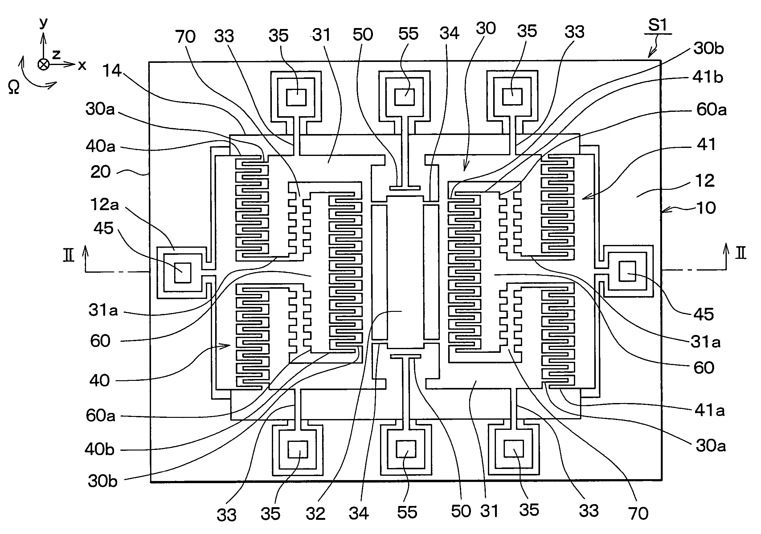
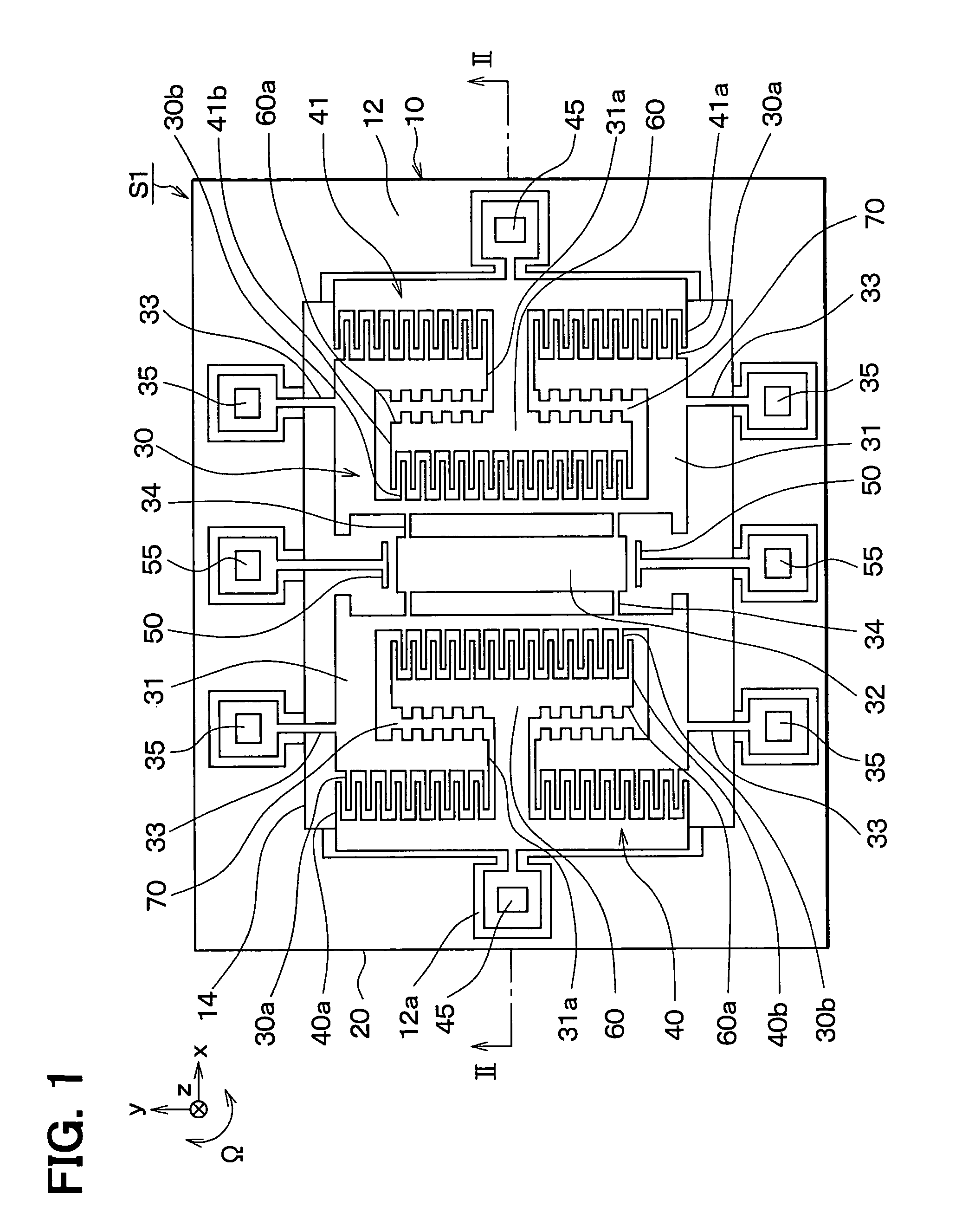
[0044]FIG. 1 is a schematic plan view showing an angular sensor S1 as an electrostatic vibration type device according to an embodiment of the present invention, and FIG. 2 is a cross-sectional view taken along A—A of FIG. 1.

[0045]As shown in FIG. 2, the substrate constituting the angular sensor S1 is a rectangular SOI substrate 10 formed by laminating a second silicon substrate 12 on a first silicon substrate 11 through an oxide film 13.

[0046]Here, the second silicon substrate 12 is subjected to an etching treatment to form grooves 12a, thereby sectioning the second silicon substrate 12 into a vibrator 30, driving electrodes 40, 41, detecting electrodes 50, respective beams 33, 34, etc.

[0047]At the portion of the SOI substrate 10 which corresponds to the vibrator 30, the first silicon substrate 11 and the oxide film 13 are removed by etching and thu...


PUM


Abstract

A vibrator has a frame portion having a planar frame shape, an in-frame fixed portion which is fixed to a base portion and located in the inner space surrounded by the inner periphery of the frame portion, and a driving electrode comprising a first driving electrode disposed so as to confront the outer peripheral portion of the vibrator, and a second driving electrode which is equipped to the in-frame fixed portion so as to confront the inner peripheral portion of the frame portion, and the back-side portion of the in-frame fixed portion and the inner peripheral portion of the frame portion confronting the back-side portion are designed in an unevenly-shaped portion.

Description

CROSS REFERENCE TO RELATED APPLICATION[0001]This application is based upon, claims the benefit of priority of, and incorporates by reference the contents of, Japanese Patent Application No. 2003-5749 filed on Jan. 14, 2003.FIELD OF THE INVENTION[0002]The present invention relates to an electrostatic vibration device for driving a vibrator with electrostatic force so that the vibrator vibrates (hereinafter referred to as “driving-vibration”), and is applicable to an electrostatic vibration type angular velocity sensor, an actuator, etc.BACKGROUND OF THE INVENTION[0003]As an electrostatic vibration type device is proposed an electrostatic vibration type angular velocity sensor in which a base portion, a vibrator and an exciting electrode for driving the vibrator are formed by etching a semiconductor substrate (for example, see JP-A-2001-91265 (pp4–5, FIG. 1)).[0004]According to this angular velocity sensor, the vibrator is driven (excited) to vibrate in a predetermined driving directi...

Claims


Application Information

Patent Timeline
IPC IPC(8): G01P9/04G01C19/56G01C19/5719G01C19/5762H02N1/00
CPCH02N1/008G01C19/5719
Inventor HIGUCHI, HIROFUMI
Owner DENSO CORP
Learn More