
Trailer position indicator

a technology of position indicator and trailer, which is applied in the field of trailers, can solve the problems of affecting the safety of passengers, braking difficulties, and presenting significant challenges to the driver of the vehicle to which the trailer is connected,

Inactive Publication Date: 2006-06-20
JAMAK FABTION TEX
View PDF21 Cites 4 Cited by
  • Summary
  • Abstract
  • Description
  • Claims
  • Application Information

AI Technical Summary

Benefits of technology

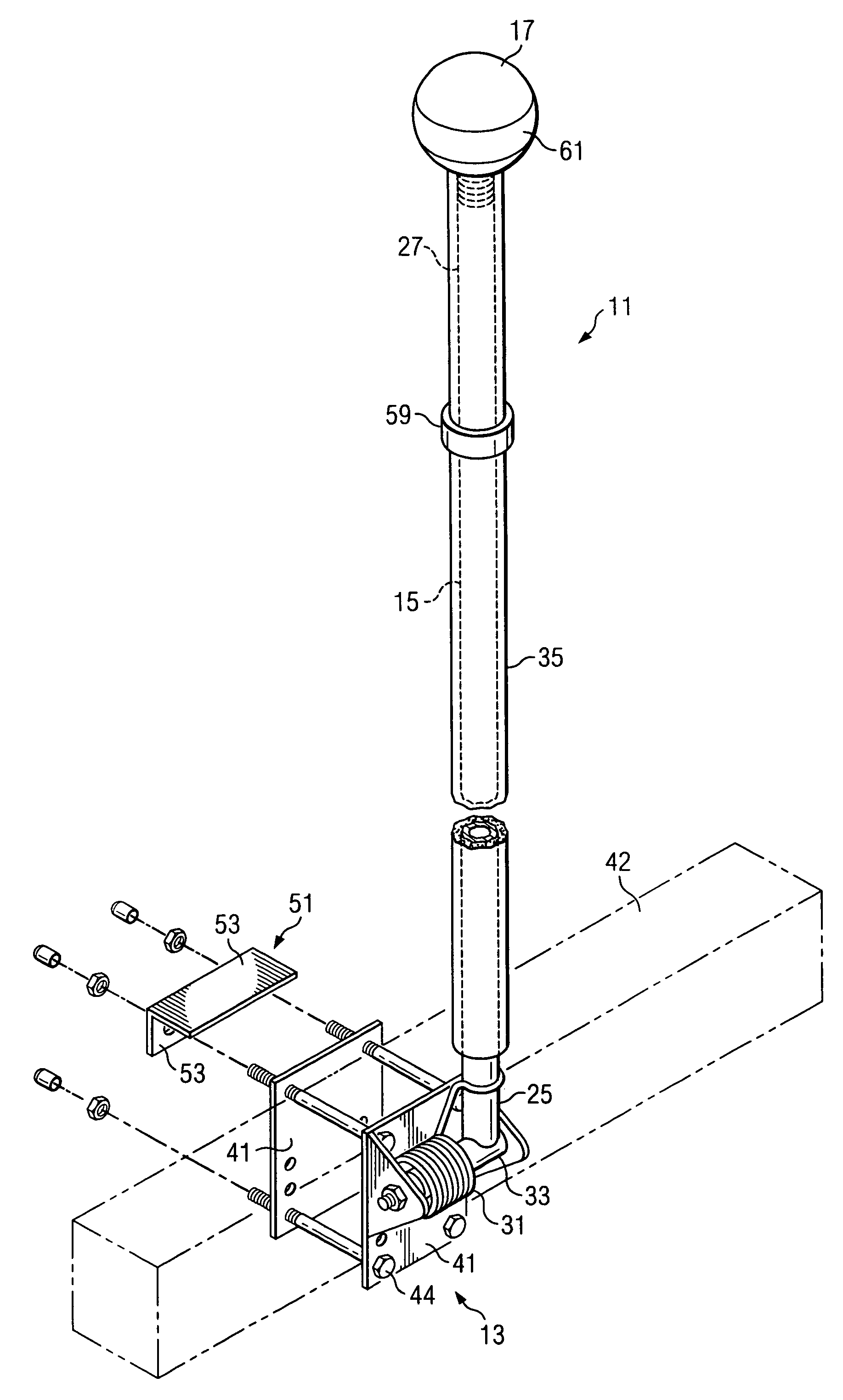
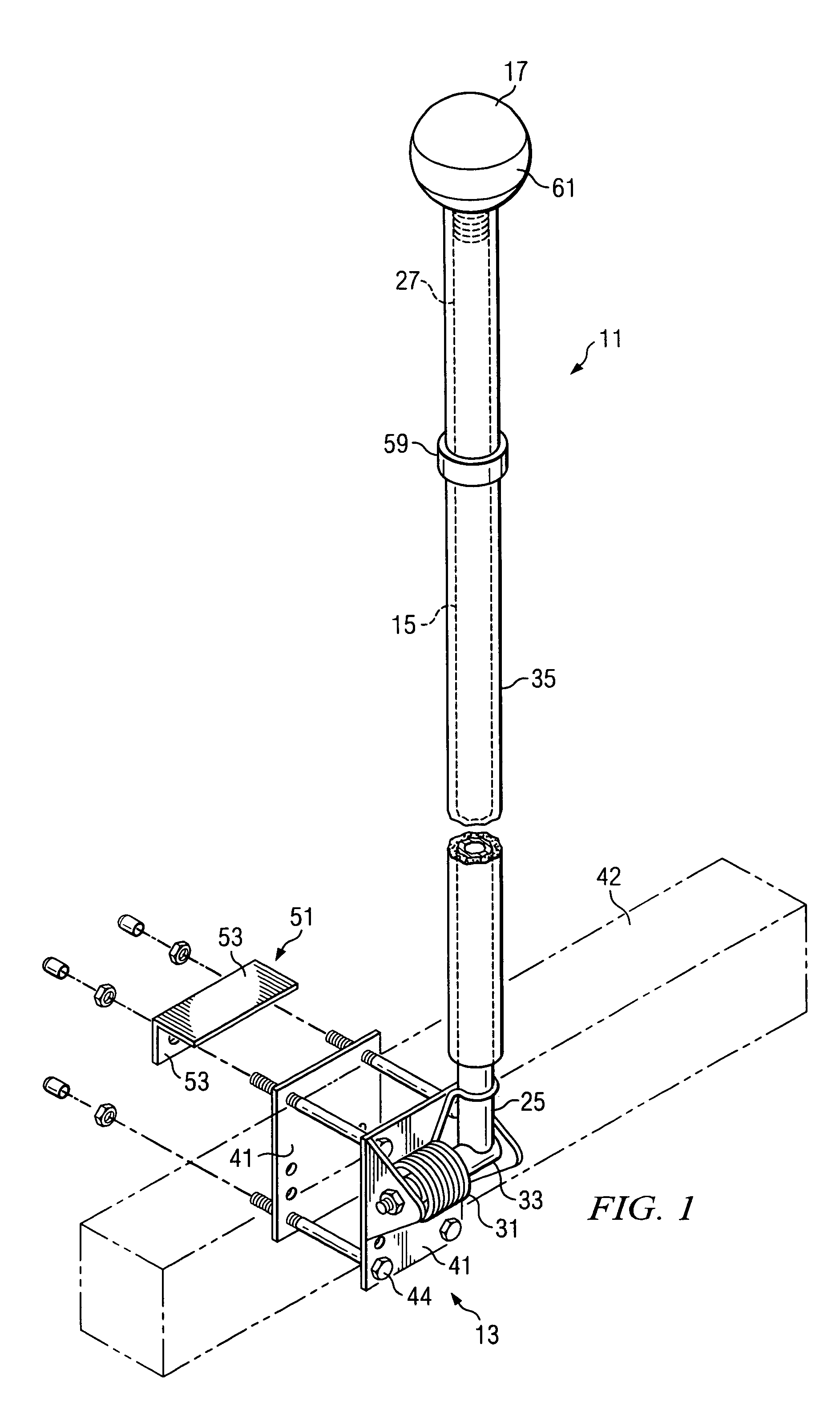
[0010]A depth ring is adjustably disposed around the boom arm for use with boat trailers. The depth ring allows a driver to determine the relative depth of the water as the boat trailer is being backed down a boat ramp.
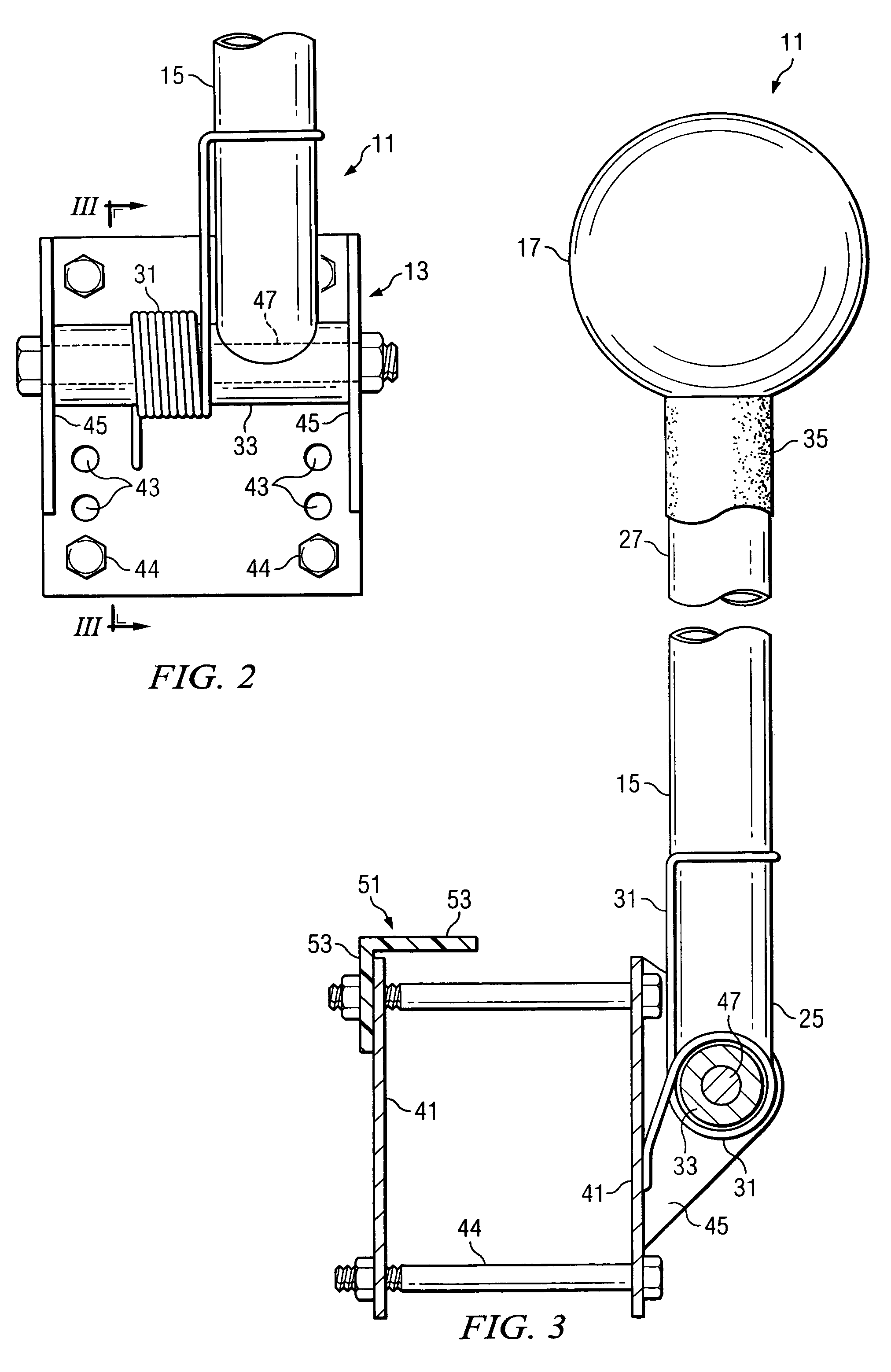
[0011]A protective sleeve is disposed on the boom arm to protect objects being loaded on the trailer as the objects come in contact with the boom arm. The protective sleeve is preferably polyurethane that is over-molded onto the boom arm for a snug fit. Another protective element is the bracket protector, which preferably is an L-shaped device that is connected to the trailer attachment member. The bracket protector prevents objects being loaded onto the trailer from contacting the trailer attachment member. Preferably, the bracket protector is made from high density polyethylene.

Problems solved by technology

Towing a trailer can present significant challenges to the driver of a vehicle to which the trailer is connected.
Also, the additional weight imposed on the vehicle by the trailer can create braking difficulties.
Drivers are required to exercise extreme caution when slowing or stopping the vehicle and the trailer because of the often diminished breaking capacity of the vehicle.
Perhaps the greatest challenge to a driver is backing the trailer.
To complicate matters further, the process of “steering” the trailer while the vehicle moves backwards is often counter-intuitive to many drivers.
Backing the trailer is made even more difficult when the driver cannot see the trailer as the driver peers through the rear window of the vehicle.
If the vehicle is a large car or truck, or if the trailer is especially short, it may not be possible to see the trailer below the rear portion of the vehicle.
However, it is very difficult for drivers not having these special skills to back an unseen trailer.

Method used


Image

  • Trailer position indicator
  • Trailer position indicator
  • Trailer position indicator

Examples


Embodiment Construction

[0020]In the following detailed description of the preferred embodiments, reference is made to the accompanying drawings, which form a part hereof, and in which is shown by way of illustration specific preferred embodiments in which the invention may be practiced. These embodiments are described in sufficient detail to enable those skilled in the art to practice the invention, and it is understood that other embodiments may be utilized and that logical mechanical, structural, and material changes may be made without departing from the spirit or scope of the invention. To avoid detail not necessary to enable those skilled in the art to practice the invention, the description may omit certain information known to those skilled in the art. The following detailed description is, therefore, not to be taken in a limiting sense, and the scope of the present invention is defined only by the appended claims.

[0021]Referring to FIGS. 1–5, a trailer position indicator 11 according to the presen...


PUM


Abstract

A trailer position indicator having a trailer attachment member, a boom arm, and a guidance member is provided. The trailer attachment member is configured to be attached to a cross member of a boat trailer. The boom arm is pivotally connected at a lower end to the trailer attachment member, and the guidance member is connected to the upper end of the boom arm. A torsion spring is operably connected to the boom arm and trailer attachment member to bias the boom arm toward an extended position, yet allow the boom arm to be pushed to a stowed position as a boat is loaded on the trailer. A bracket protector is attached to the trailer attachment member and a protective sleeve is disposed on the boom arm for protecting the boat during loading and unloading.

Description

CROSS-REFERENCE TO RELATED APPLICATIONS[0001]This application claims the benefit of U.S. Provisional Application No. 60 / 465,051 filed Apr. 24, 2003, which is hereby incorporated by reference.BACKGROUND OF THE INVENTION[0002]1. Field of the Invention[0003]This invention relates generally to trailers and in particular to a position indicator that allows a driver to quickly and easily determine a position of a trailer in tow.[0004]2. Description of Related Art[0005]Towing a trailer can present significant challenges to the driver of a vehicle to which the trailer is connected. The driver must remain mindful about the trailer's size, weight, and location at all times. For example, if the trailer is wider than the vehicle or the load carried by the trailer is taller than the vehicle, the driver must vigilantly ensure that the trailer and its load do not impact vehicles, buildings, road signs, bridges, or other structures near the road. When rounding corners, trailers tend to take a less-...

Claims


Application Information

Patent Timeline
Patent Type & Authority Patents(United States)
IPC IPC(8): B60Q1/48B60D1/36B60D1/58
CPCB60D1/36
Inventor EMERSON, BLAIRHYER, MICHAEL L.
Owner JAMAK FABTION TEX
Learn More