

Method for the automatic control of an internal combustion engine-generator unit
- Summary
- Abstract
- Description
- Claims
- Application Information
AI Technical Summary
Benefits of technology
Problems solved by technology
Method used
Image

Examples
first embodiment
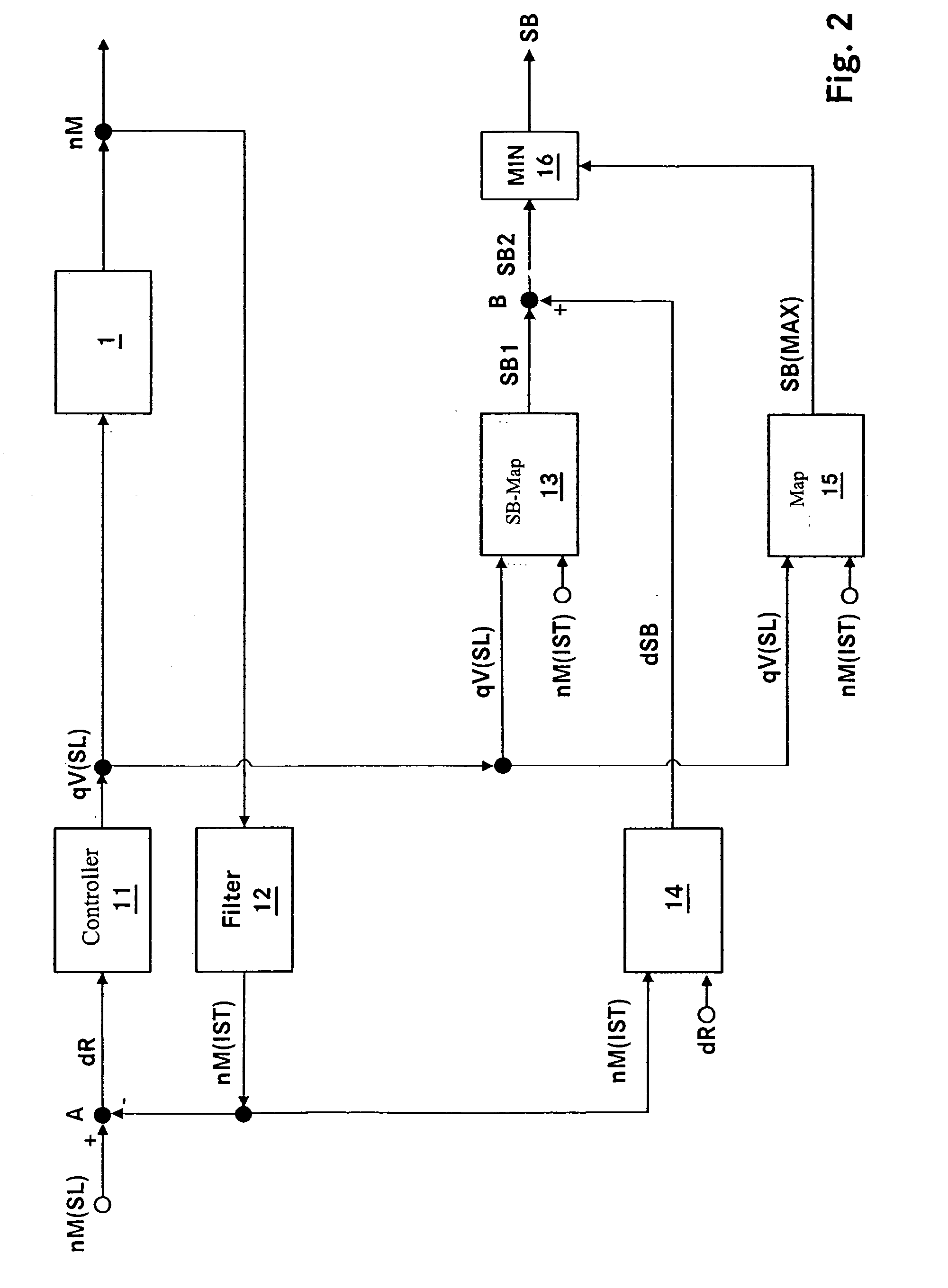
[0030]FIG. 5 shows a functional block diagram for computing the injection start with filtering in accordance with a The functional block diagram is essentially the same as the functional block diagram in FIG. 2. In contrast to the latter, a filtered input variable is supplied to the injection start input-output map 13. The filtered input variable corresponds either to a filtered set injection quantity qV(F) or to an integral portion of the set injection quantity qV(I). The filtered set injection quantity qV(F) is computed from the set injection quantity qV(SL) by means of a filter 21. The integral portion of the set injection quantity qV(I) is computed by the speed controller 11, which in practice is realized, for example, as a PIDT1 controller. The input variable of the injection start input-output map 13 is selected by a switch 22. Especially quiet engine running in steady-state operation is achieved by the filtering of the input variable of the injection start input-output map 1...
second embodiment
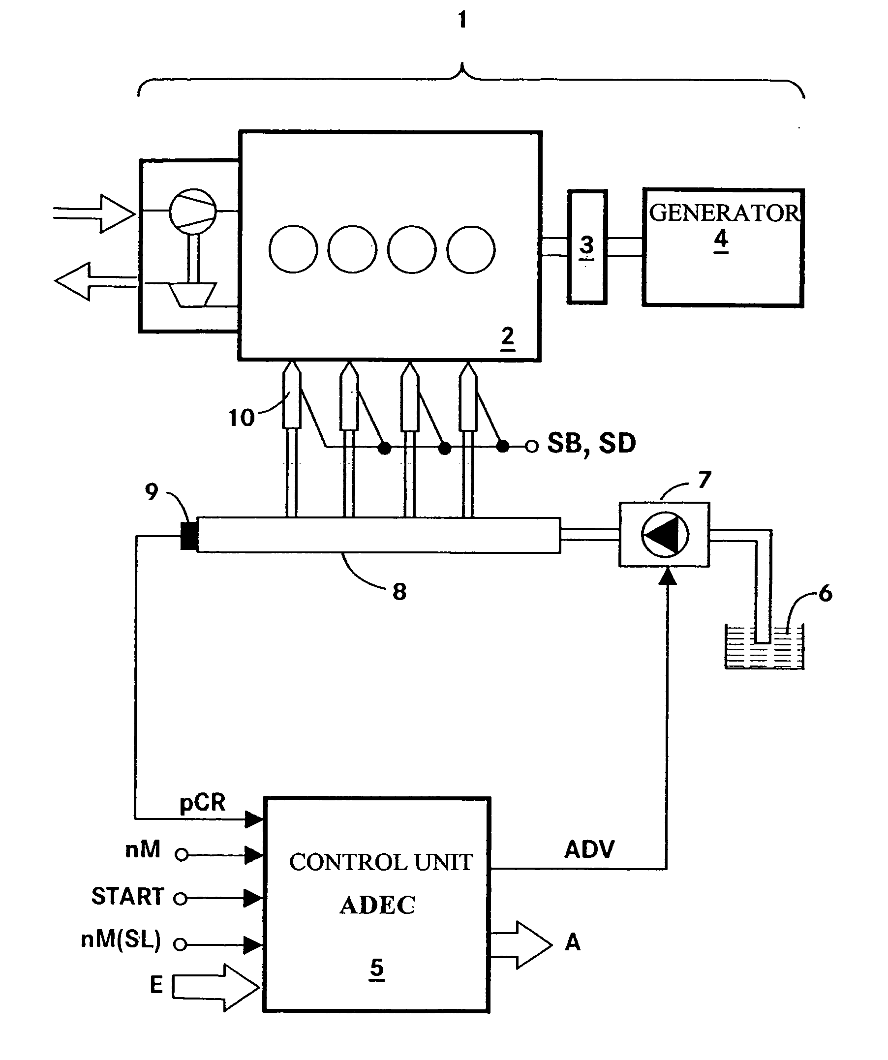
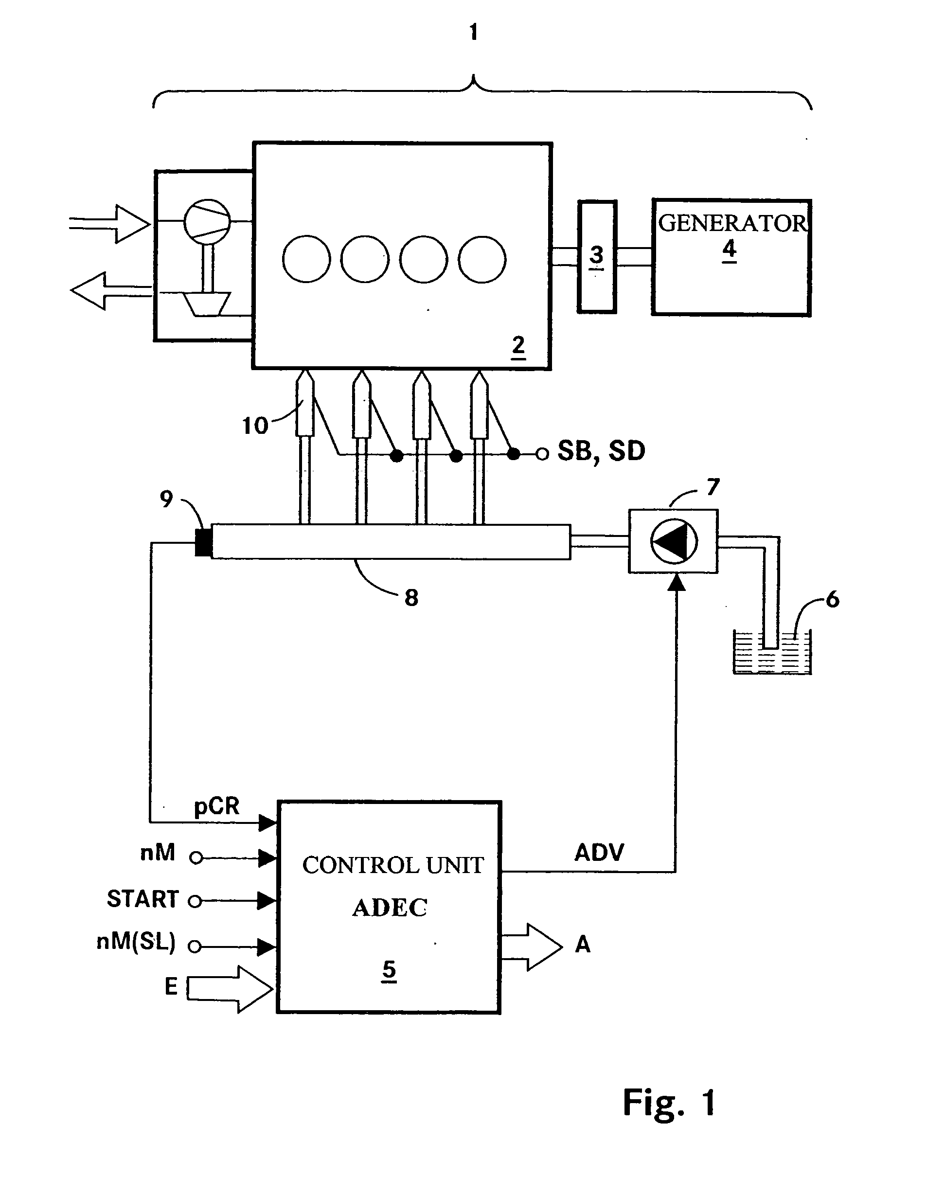
[0031]FIG. 6 shows a functional block diagram for determining the injection start with filtering in accordance with a This functional block diagram is essentially the same as the functional block diagram in FIG. 2. It differs from the latter in that the first injection start SB1 is additionally converted by a filter 23 to a first filtered injection start SB1(F), which is combined at summing point B with the injection start correction dSB. The system functions as described in connection with FIG. 2.
[0032]FIG. 7 has four parts 7A to 7D, which show, in each case, as a function of time: a signal power consumption P (FIG. 7A), the behavior of the set speed / actual speed nM(SL) / nM(IST) and of the set injection quantity qV(SL) (FIG. 7B), the behavior of the first injection start SB1 and the injection start correction dSB (FIG. 7C), and the behavior of the resulting injection start SB (FIG. 7D). In FIG. 7B, the actual speed nM(IST) is drawn as a solid line, the set speed nM(SL) is drawn as ...
PUM
 Abstract
Description
Claims
Application Information