Dc/dc converter

a converter and converter technology, applied in the direction of electric variable regulation, process and machine control, instruments, etc., can solve the problems of high cost, inability to adjust the brightness of leds, etc., to achieve the effect of saving space and inexpensive solution

Active Publication Date: 2011-04-21
LEAR CORP GMBH
View PDF5 Cites 10 Cited by
  • Summary
  • Abstract
  • Description
  • Claims
  • Application Information

AI Technical Summary

Benefits of technology

[0010]The object of the present invention is to provide a DC/DC converter that handles this problem. It is additionally the object of the pr...

Problems solved by technology

Problematic in the known state of the art, however, is that a substantial expense is required in regard to the number of components to be used and in regard to the brightness control of the LED...

Method used


Image

  • Dc/dc converter
  • Dc/dc converter
  • Dc/dc converter

Examples


Embodiment Construction

[0035]In the following description of the figures, the same reference characters for identical elements in the figures will be used for all of the figures. This will provide clarity and better understanding of the following concrete description of the invention based on figures FIG. 1 to FIG. 9.

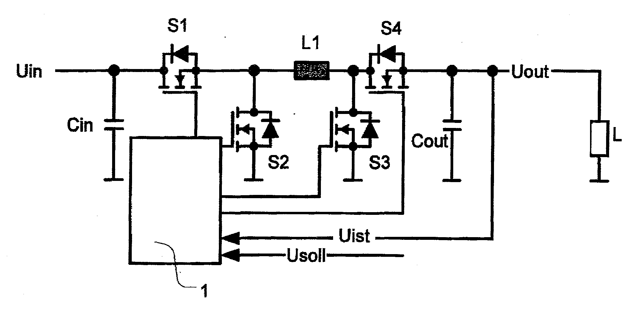
[0036]The following description based on concrete embodiment examples will discuss a “control unit” and use the verb “to control.” But at the same time, there will be no distinction between open-loop control and closed-loop control.

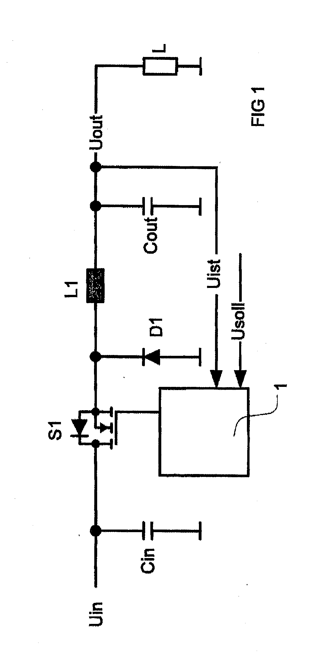
[0037]FIG. 1 shows a DC / DC converter in the form of a step-up converter. An input voltage Uin is fed to the step-up converter. An input capacitor Cin is at ground or zero point relative to the input voltage Uin. An electronic switch S1, which is driven by a control unit 1, is connected to the input capacitor Cin. The output of the electronic switch 1 leads to a diode D1, which leads to ground or zero point in the reverse direction. On the voltage side, an inductor ...


PUM


Abstract

A DC/DC converter converts an input DC voltage into an output DC voltage. The DC/DC converter includes an input capacitor, an inductor, an electronic switch, a diode, an output capacitor and a control unit, wherein the control unit controls the first electronic switch as a function of the signals fed to the control unit. The input capacitor is connected between the input voltage and ground or zero point, and the inductor is connected between the input capacitor and the electronic switch. A second electronic switch, which the control unit can drive by means of a switching signal, is disposed between the load and the ground or zero point, and a second diode embodies a connection between the output of the load and the input capacitor. The control unit is fed the value of the input voltage.

Description

CROSS-REFERENCE TO RELATED APPLICATIONS[0001]This application claims the benefit of German Patent Application No. 10 2009 003 852.3 filed Apr. 30, 2009, the disclosure of which is incorporated herein by reference.BACKGROUND OF THE INVENTION[0002]The present invention relates to a DC / DC converter for operating a load, especially an electrical load comprising light-illuminating diodes or LEDs.[0003]Constant-current sources are primarily used to control an electrical load, especially a load of LEDs, LED chains and / or LED arrays. Diverse arrangements of LEDs are known; besides parallel and matrix connection of LEDs, the possibility of series connection of LEDs is known. In a series connection of LEDs, all LEDs are connected behind one another in a row; this connection is also called an LED chain. In order to operate LED chains, a constant current is generated and conducted through the LEDs. A voltage that corresponds to the sum of the forward voltages of all LEDs then appears across the...

Claims


Application Information

Patent Timeline
IPC IPC(8): H05B37/00G05F1/618H05B45/50
CPCH02M3/156H05B33/0815Y02B20/346H05B33/089H05B33/0818H05B45/50Y02B20/30H05B45/3725H05B45/38
Inventor KRAPP, OLIVERGREBNER, KLAUS-DIETER
Owner LEAR CORP GMBH
Why Eureka
Try Eureka