Electric power supply device

a technology of power supply device and power supply device, which is applied in the direction of process and machine control, instruments, pulse technique, etc., can solve the problems of semiconductor element (tb>101/b>) not being able to reset to a turning on state, and the comparator cmp b>102/b> does not function

Active Publication Date: 2010-05-27
YAZAKI CORP
View PDF27 Cites 10 Cited by
  • Summary
  • Abstract
  • Description
  • Claims
  • Application Information

AI Technical Summary

Benefits of technology

[0026]In the above-described structure, when the first voltage is abruptly lowered due the short-circuit of a wiring such as a dead short-circuit, since the semiconductor element is turned off before the first voltage is lower than a lower limit value of an in-phase input voltage of a comparator, a malfunction may be prevented from occurring and the semiconductor element may be assuredly turned off to protect the load circuit.
[0027]In the above-described structure, when the plurality load circuits are provided in parallel, if a dead short-circuit occurs in one load circuit and the first voltage is abruptly lowered, since the semiconductor elements are turned off before the first voltages are lower than the lower limit value of the in-phase input voltage of the comparator in the operating load circuits of the plurality of load circuits, the malfunctions may be prevented from occurring respectively in the load circuits and the semiconductor elements may be assuredly turned off to protect the load circuits.
[0028]In the above-described structure, when the first voltage is abruptly lowered to be lower than the first decided voltage L-V1, a retry operation is carried out. When the semiconductor element is turned on, if the first voltage V1 is lower than the first decided voltage continuously N1 times (the first prescribed number of times), the turning-off state of the semiconductor element is held. Accordingly, when the wiring is not short-circuited, for instance, when the voltage V1 is lowered due to an imperfect contact of a connector, the turning on state of the semiconductor element may be maintained to continuously drive the load circuit.
[0029]In the above-described structure, the first decided voltage L-V1 and the second decided voltage V3 higher than the first decided voltage L-V1 are set. After the first voltage V1 is lower than the first decided voltage L-V1, the retry operation is carried out. When the semiconductor is turned on, if the voltage V1 showing “V1<L-V1” appears continuously N1 times (the first prescribed number of times) or if the voltage V1 showing “L-V1<the minimum value of V1<V3” appears continuously N2 times (the second prescribed number of times), the turning-off state of the semiconductor element is held. Accordingly, when the short-circuit of the wiring such as the dead short-circuit occurs, the turning off state of the semiconductor element may be assuredly held to protect the load circuit.
[0030]When the voltage V1 is lowered due to an imperfect contact of a connector provided in the wiring of a load side, the voltage V1 showing “V1<L-V1” or “L-V1<the minimum value of V1<V3” appears, however, the number of times of the appearances of V1 do not reach the above-described prescribed number times N1 and N2. Accordingly, when the voltage V1 is lowered due to the imperfect contact, the turning off state of the semiconductor element is not held so that the load circuit may be operated.
[0031]In the above-described structure, the short-circuit of the wiring such as the dead short-circuit occurs to carry out the retry operation. When the semiconductor element is turned on, if the voltage V1 shows “L-V1<the minimum value of V1<V3”, the second decided voltage V3 is changed to be gradually increased. Accordingly, when the dead short circuit occurs, the voltage V1 may be prevented from showing “V1<L-V1” or “L-V1<the minimum value of V1<V3” to assuredly hold the turning off state of the semiconductor element and protect the load circuit.

Problems solved by technology

As described above, in an over-current protecting device shown in FIG. 9, when the voltage V1 is extremely lowered to become a lower limit of the in-phase input range of the comparator CMP 102 or lower, a problem arises that the comparator CMP 102 does not function.
Thus, when the instantaneously interrupted source voltage is recovered to a normal voltage, a problem arises that the semiconductor element (T101) cannot be reset to a turning on state.

Method used


Image

  • Electric power supply device
  • Electric power supply device
  • Electric power supply device

Examples


first embodiment

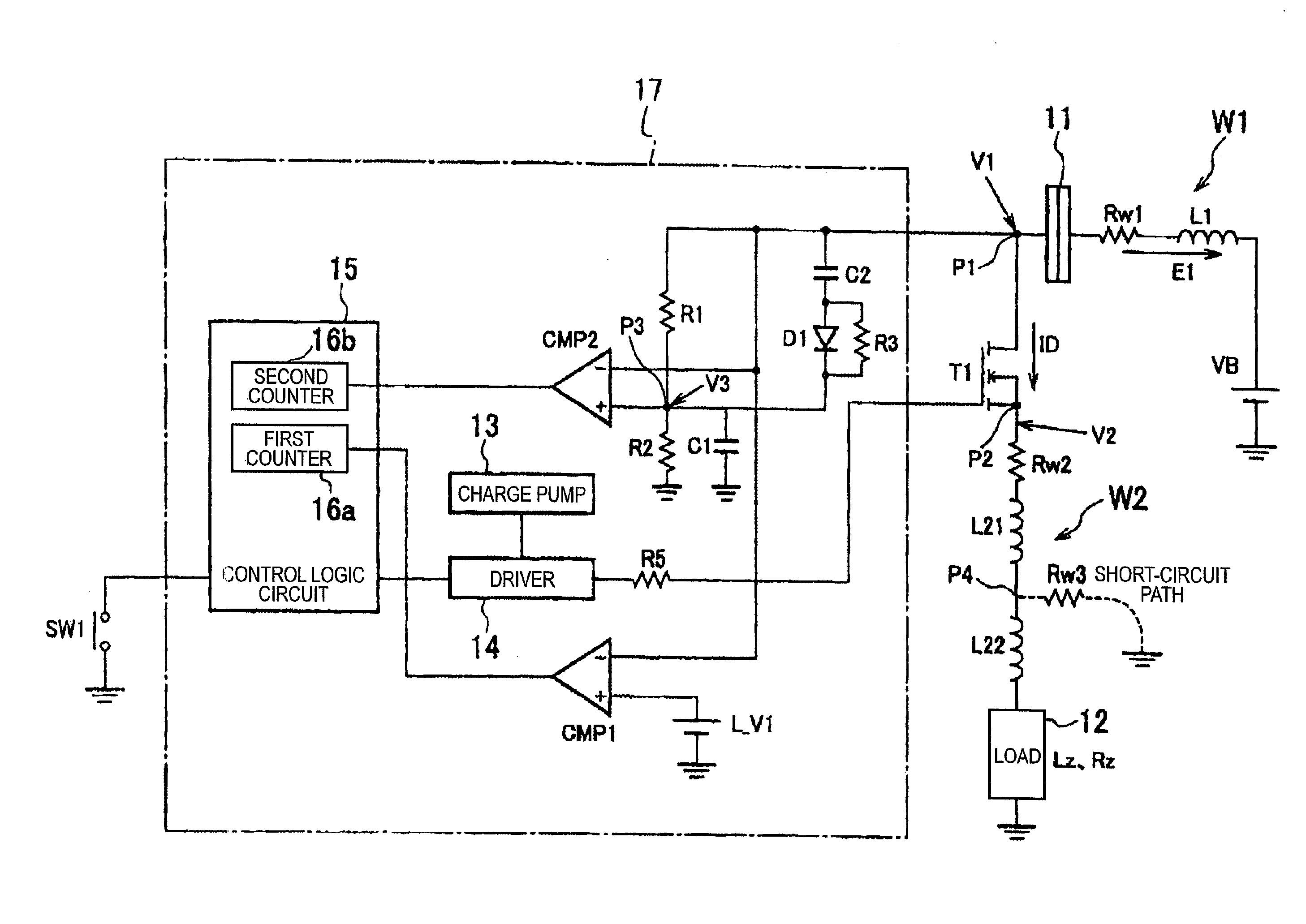
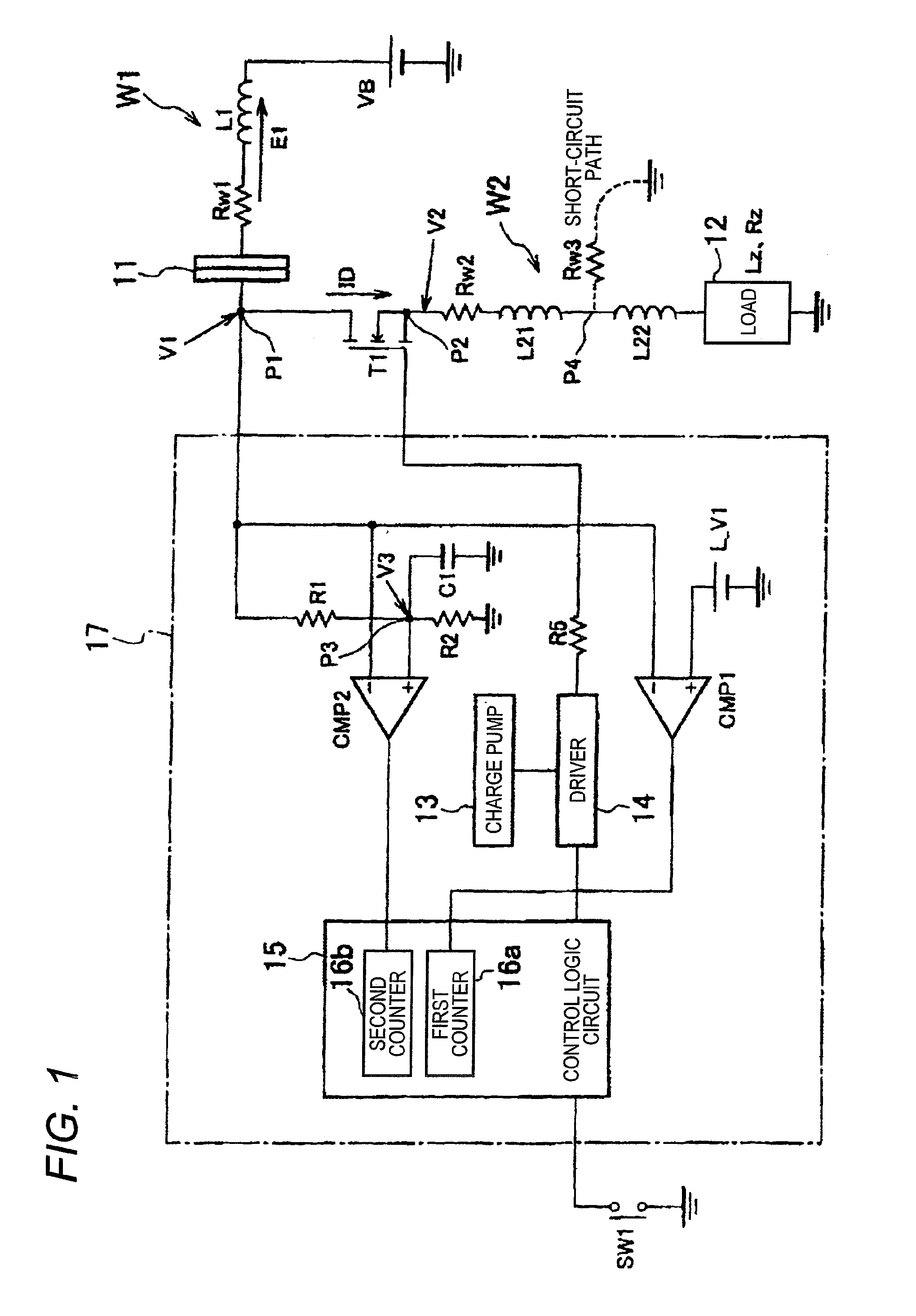
[0044]Now, an embodiment of the present invention will be described by referring to the drawings. FIG. 1 is a circuit diagram showing the structure of an electric power supply device according to the present invention.

[0045]The electric power supply device shown in FIG. 1 supplies an electric power of a battery to a load such as a lamp or a motor mounted on, for instance, a vehicle to drive the load. A semiconductor element T1 such as an MOSFET is provided between a load 12 and a battery VB (for instance, DC 12V) to switch a tuning on and off of the semiconductor T1 so as to control the drive and stop of the load 12.

[0046]A drain (a point P1, a first main electrode) of the semiconductor element T1 is connected to a connector 11. The connector 11 is connected to a positive terminal of the battery VB through a wiring W1 of a power source side. Further, a source (a point P2, a second main electrode) of the semiconductor element T1 is connected to an end of the load 12 through a wiring ...

second embodiment

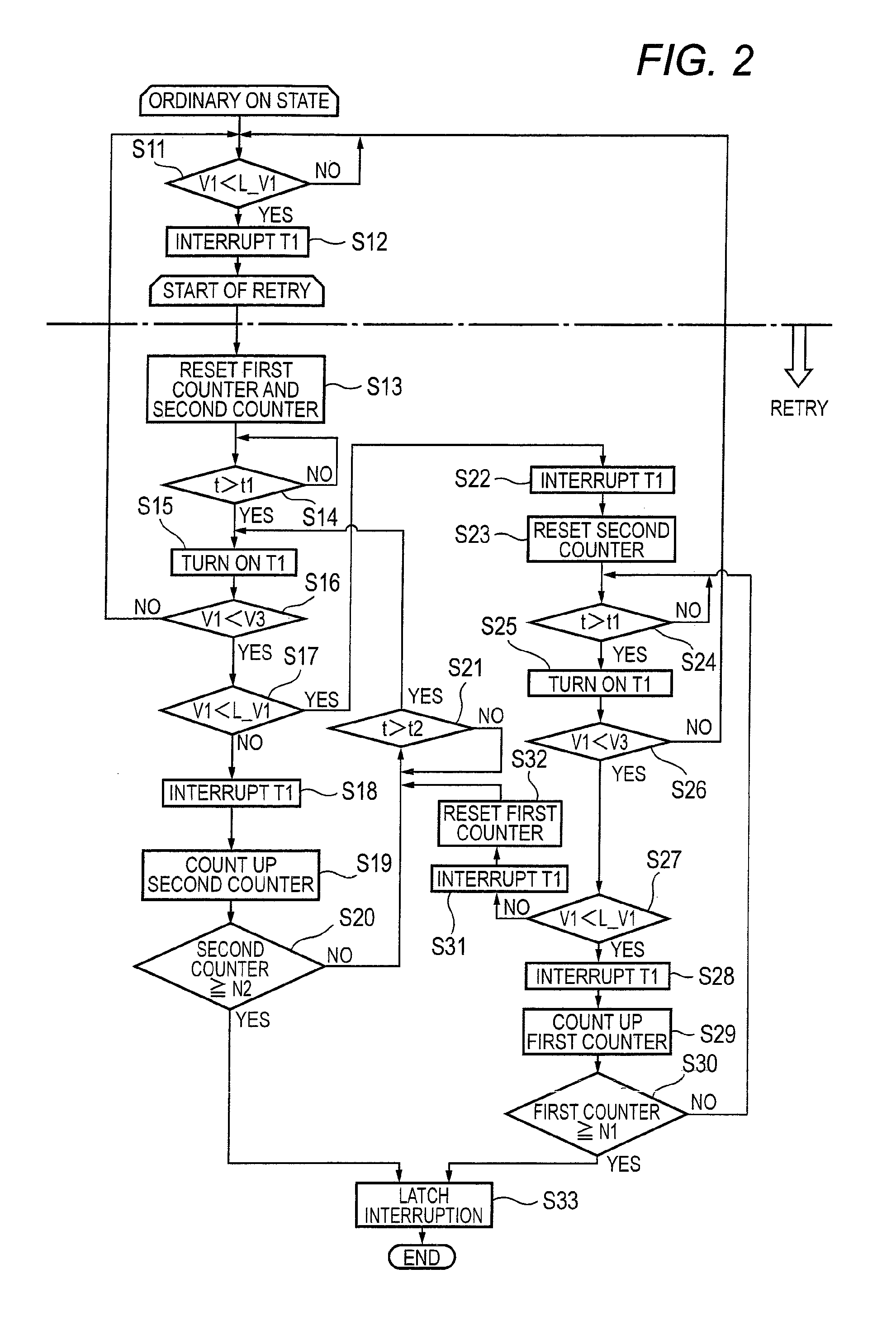
[0084]As a result, since the dead short circuit occurs, the first counter 16a or the second counter 16b needs to continuously count up and hold the semiconductor element T1 in an interrupted state, however, the voltage V1 may occasionally vary above and below the first decided voltage L-V1 to continuously carry out the retry operation. In an electric power supply device of the second embodiment assuredly discriminates, in such a case, the change of a voltage V1 due to a dead short-circuit from the change of the voltage V1 due to an imperfect contact of a connector to control a semiconductor element T1 to be turned on and off.

[0085]FIG. 7 is a circuit diagram of the electric power supply device according to the second embodiment. As shown in FIG. 7, a circuit shown in FIG. 7 is different from the circuit shown in FIG. 1 in a point that a capacitor C2, a diode D1 and a resistance R3 are added. That is, a series connecting circuit of the capacitor C2 and the diode D1 is inserted betwee...


PUM


Abstract

In an electric supply device of the present invention, since a semiconductor element T1 is interrupted before a drain voltage V1 of the semiconductor element T1 is lower than an in-phase input minimum voltage, a load circuit can be assuredly protected. Further, assuming that a first decided voltage is L-V1 and a second decided voltage V3, when the voltage V1 becomes “V1<L-V1”, a retry operation is carried out. When the number of times of “V1<L-V1” reaches N1 times, or when the number of times of “L-V1<V1<V3” reaches N2 times, an interrupted state of the semiconductor element T1 is held to protect the load circuit. Further, when the voltage V1 suddenly drops due to an imperfect contact of a connector 11, a minimum value of the voltage V1 is not a stable value and the interrupted state of the semiconductor T1 is not held.

Description

TECHNICAL FIELD[0001]The present invention relates to an electric power supply device for supplying an electric power to a load by controlling a semiconductor element to be turned on and off, and more particularly to a technique for instantaneously interrupting a circuit when a wiring is short-circuited.BACKGROUND ART[0002]As a usual electric power supply device, for instance, a device is known that is disclosed in JP-A-2006-5581 (patent literature 1).[0003]FIG. 9 is a circuit diagram of the device disclosed in the patent literature 1. A circuit shown in FIG. 9 supplies an electric power of a battery to a load such as a lamp or a motor mounted on, for instance, a vehicle to drive the load. In the circuit, a semiconductor element (T101) such as an MOSFET is provided between a load 102 and a battery VB to switch turning on and off of the semiconductor element (T101) so that the load 102 is controlled to be driven and stopped.[0004]A drain (a point P1) of the semiconductor element (T10...

Claims


Application Information

Patent Timeline
Patent Type & Authority Applications(United States)
IPC IPC(8): G05F1/00H02M1/00
CPCB60Q11/00H03K17/0822H02H3/087H05B39/04H03K17/302
Inventor OHSHIMA, SHUNZOU
Owner YAZAKI CORP
Why Eureka
Try Eureka