Method and apparatus for retrieving energy from a flowing stream of water

a technology of water flowing and energy retrieval, applied in the direction of electric generator control, vessel construction, marine propulsion, etc., can solve the problems of limiting the amount of power that can be generated, the width of the channel is somewhat limited, and the structure cannot be moved from one location to another, so as to achieve the effect of convenient movemen

Inactive Publication Date: 2006-06-20
VOVES JOSEPH
View PDF13 Cites 52 Cited by
  • Summary
  • Abstract
  • Description
  • Claims
  • Application Information

AI Technical Summary

Benefits of technology

[0010]It is a principal object of the present invention to provide a system, including both a method and apparatus, for retrieving energy from a flowing stream of water, such as a river or tidal flow, which can be easily moved to a convenient location and which is capable of capturing a significant portion of the energy of the flowing stream.
[0013]Preferably, the energy of the flowing water is converted into mechanical energy by means of a plurality of movable paddles which intercept all of the water flowing through the hull. In this way, once water enters the hull, nearly all of its energy can be converted into mechanical energy; that is, the energy of a rotating shaft. By conforming the size and shape of the paddles to that of the hull, water is prevented from diverting around, and bypassing the paddles as it flows through the hull.
[0016]Following its operation in one location, when the boat is to be moved to a new location, the hinged members at the bow of the boat are first closed, preventing new water from entering the hull. The hull is then emptied of water by moving the paddles and causing the water to exit through the stern. Thereafter, the hinged member at the stern is closed and the remaining water in the hull is removed (if desired) by means of a pump. Once emptied of water, the hull may be easily moved.

Problems solved by technology

A disadvantage is that the flowing stream may easily divert around, and thus bypass the paddles of the water wheels, limiting the amount of power that can be generated.
However, the width of this channel is somewhat limited and, once fixed in place, the structure cannot be moved from one location to another.
While these devices have the advantage of being mobile, like the “electric float” of Pattosien, they are unable to convert a significant portion of the energy of a flowing stream into mechanical or electrical energy.
All of these devices are rigid structures, however, and are not designed to be moved from place to place.

Method used


Image

  • Method and apparatus for retrieving energy from a flowing stream of water
  • Method and apparatus for retrieving energy from a flowing stream of water
  • Method and apparatus for retrieving energy from a flowing stream of water

Examples


Embodiment Construction

[0024]The preferred embodiments of the present invention will now be described with reference to FIGS. 1–6 of the drawings. Identical elements in the various figures are designated with the same reference numerals.

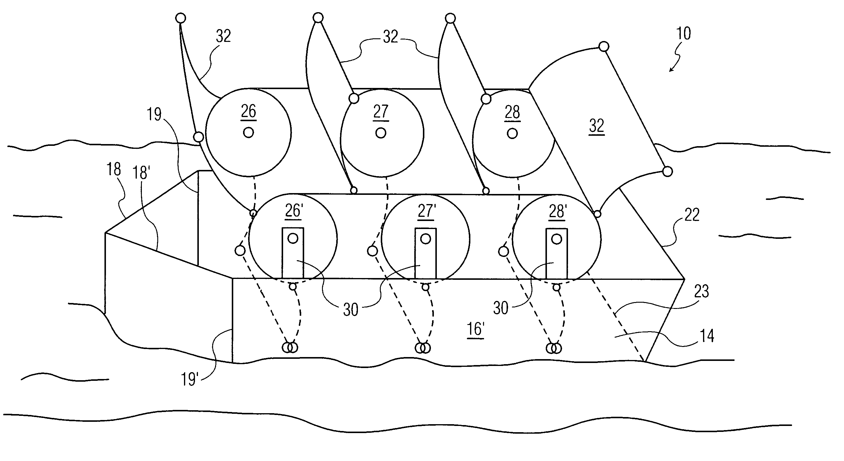
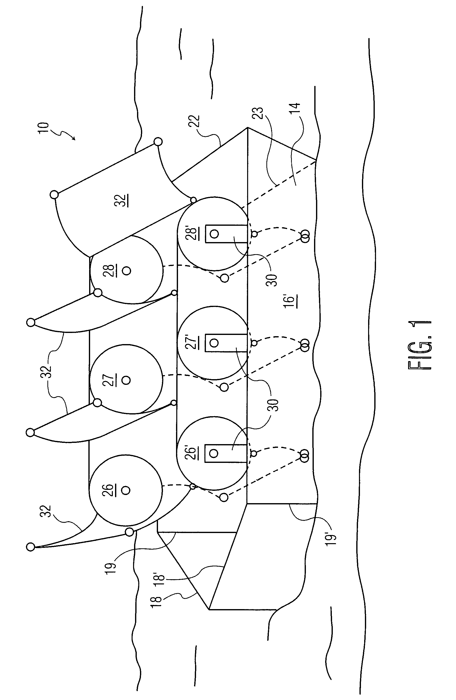
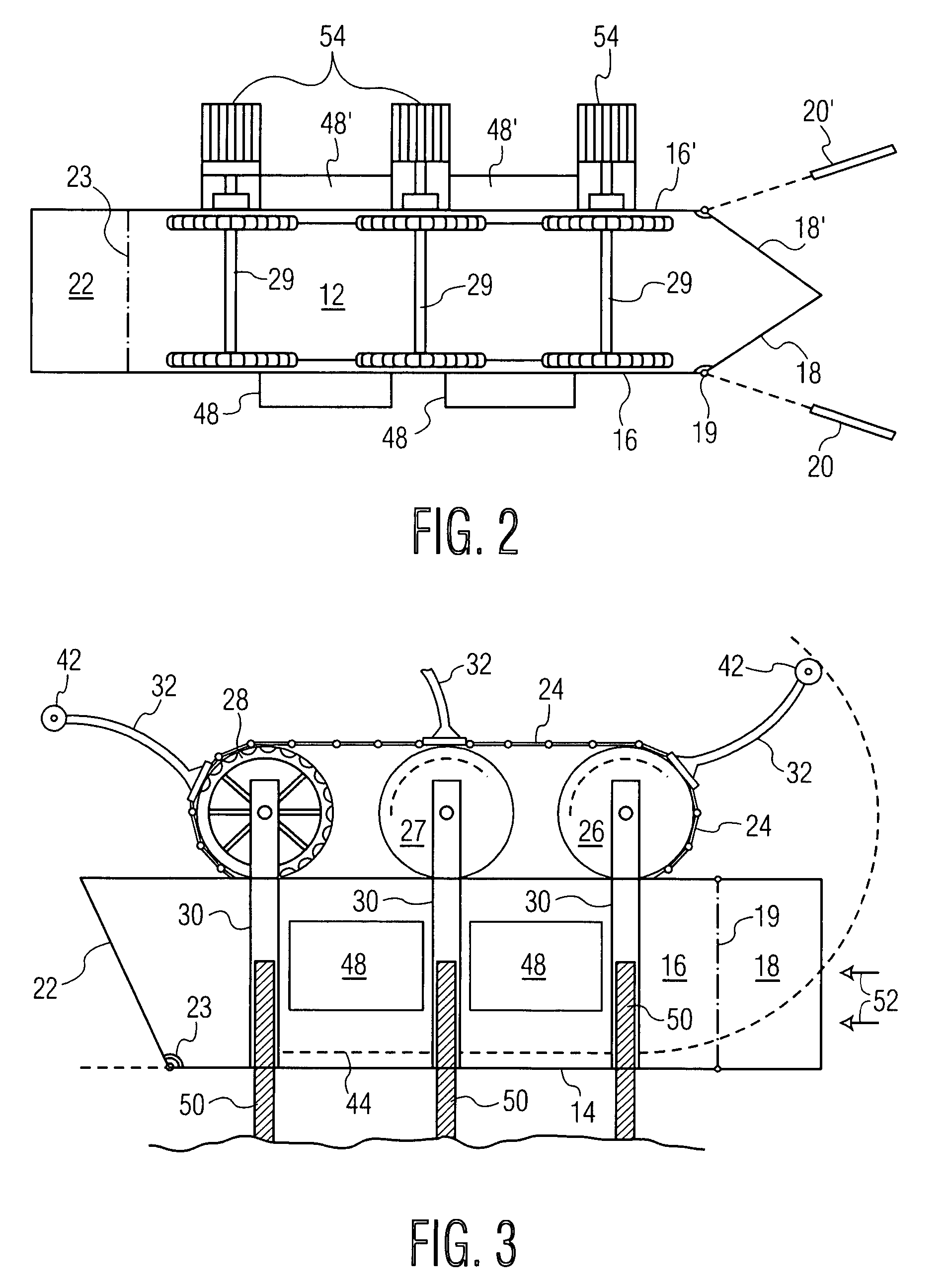
[0025]The preferred embodiment of the mobile apparatus for retrieving energy from a flowing stream of water is illustrated in FIGS. 1–3 of the drawings. As is shown there, the apparatus comprises a boat 10 having an elongate hull 12 formed by a flat, horizontal bottom 14 and two upright, flat sides 16 and 16′ on starboard and port, respectively. The bow or prow of the boat is formed by two upright flat members 18, 18′ arranged in an inverted (upside down) V configuration. These members are hinged to the sides of the hull 16, 16′, respectively, about substantially vertical hinge lines 19, 19′, respectively. The hinged members 18, 18′ are sealed together at the prow and sealed to the bottom 14 of the boat when they are in a closed position. During operation, these members ma...


PUM


Abstract

A boat for retrieving energy from a flowing stream of water, such as a river or tidal flow, which can be easily moved to a convenient location and which is capable of capturing a significant portion of the energy of the flowing stream. The boat has a bottom and two sides, forming an elongate hull with a bow and a stern at opposite ends, and means for anchoring the boat to hold it stationary in a stream of water. The boat has openable hinged members at the bow and stern to allow water to enter the interior of, and to flow through, the hull from one end to the other. Devices such as paddles are arranged inside the hull for converting energy of the water flowing through the hull into mechanical energy of a rotating shaft.

Description

[0001]This appln claims benefit of 60 / 590,147, filed Jul. 22, 2004.BACKGROUND OF THE INVENTION[0002]The present invention relates to a method and apparatus for obtaining energy, particularly electrical energy, from a flowing stream such as a river, tidal basin or the like.[0003]Many types of apparatus have been devised to convert the energy of a flowing stream of water into useable mechanical energy or electricity.[0004]U.S. Pat. No. 904,892 to Pattosien discloses a “stream power electric float” which may be anchored in a stream so that the water flows beneath it. Two giant paddle wheels, mounted for rotation on the float, are driven by the flowing stream beneath the float. These paddle wheels are coupled by drive belts to an electric generator.[0005]One advantage of this device is that it may be towed by a tugboat, motor boat or the like to a desired location, adjacent to where electrical power may be needed. A disadvantage is that the flowing stream may easily divert around, and t...

Claims


Application Information

Patent Timeline
Patent Type & Authority Patents(United States)
IPC IPC(8): B63H21/20
CPCB63B35/44F03B17/064Y02E10/28B63B2035/4466Y02E10/30Y02E10/20
Inventor VOVES, JOSEPH
Owner VOVES JOSEPH
Why Eureka
Try Eureka