
Techniques for sensing chloride ions in wet or dry media

a chloride ion and sensing technology, applied in the field of sensors, can solve the problems of low adherence of pyrrole, low adherence rate, and low cost of these measurements, and achieve the effect of improving adherence ra

Inactive Publication Date: 2006-06-20
THE JOHN HOPKINS UNIV SCHOOL OF MEDICINE
View PDF1 Cites 18 Cited by
  • Summary
  • Abstract
  • Description
  • Claims
  • Application Information

AI Technical Summary

Benefits of technology

The patent describes techniques for measuring chloride ions in various media, including wet or dry conditions. The techniques involve using a sensor with a pair of electrodes and a conductive polymer film that is imprinted for uptake of chloride ions. The film is in contact with both electrodes and its electrical conductivity depends on the amount of chloride ions taken up by the film. The sensor can be embedded in concrete to measure chloride ion concentrations and determine the progress of rebar corrosion. The invention also includes an apparatus for long-term monitoring of chloride ion concentrations and a method for fabricating the chloride sensor.

Problems solved by technology

The structure is not thoroughly sampled, mostly due to economic limitations.
The cost of these measurements is high because of installation and monitoring requirements.
This approach doesn't detect degradation until it has already reached an advanced state.
When advanced degradation does occur, the corrective actions are more expensive than if the progress of degradation had been detected at a less advanced stage.
Additional costs are incurred because the resources consumed to repair a highly degraded structure diminish scheduled repairs and maintenance for other structures.
In addition, costs are imposed on the users of those structures, as their travel or utilization is diverted for extended periods of time.
For example, in bridge decks, corrosion of rebar is the primary cause of degradation.
While suitable for many purposes, a sensor based on Ag / AgCl wire electrodes suffers from some disadvantages.
One disadvantage is that the longevity of the Ag / AgCl wire electrodes is limited to about three months of operation when imbedded in concrete, well short of the decades of life desirable for monitoring bridge decks.
The functionality of the silver electrodes is of limited duration due to the high pH (alkalinity) in concrete.
The thin coatings of AgCl are likely to degrade with the repeated attack of large amounts of hydroxide.
Another disadvantage of the sensor based on Ag / AgCl wire electrodes is that it is insensitive to low chloride ion concentrations.
A further disadvantage is that the Ag / AgCl wire electrodes must be wet, in order that environmental chloride ions are mobile between the electrodes at the time of the measurement.
This is a disadvantage for making measurements in concrete that is dry.
Concrete in infrastructures is often dry at times when it is convenient to make measurements, and concrete at several inches from the surface may be dry even after many rain events.
A further disadvantage is that the electrodes are formed as wires that extend into the medium.
Such extensions are easily damaged during a process to embed the sensors in the medium.
Further disadvantages occur under freezing conditions.
Upon freezing this electrolyte precipitates its ionic constituents; and those constituents may not re-dissolve well.
Also, as with no moisture, frozen moisture does not allow mobile ions that provide a conductive path to support a voltage measurement between electrodes.
One disadvantage is that the reference electrode and polymer-coated electrode must be wet.
As stated above, this is a disadvantage for making measurements in concrete that is often dry.
A second disadvantage is that the sensor is not designed for the high alkaline levels found in concrete (pH greater than 10).
A third disadvantage is that the electrodes are formed as wires that extend into the medium and are easily damaged during a process to embed the sensors in the medium.

Method used


Image

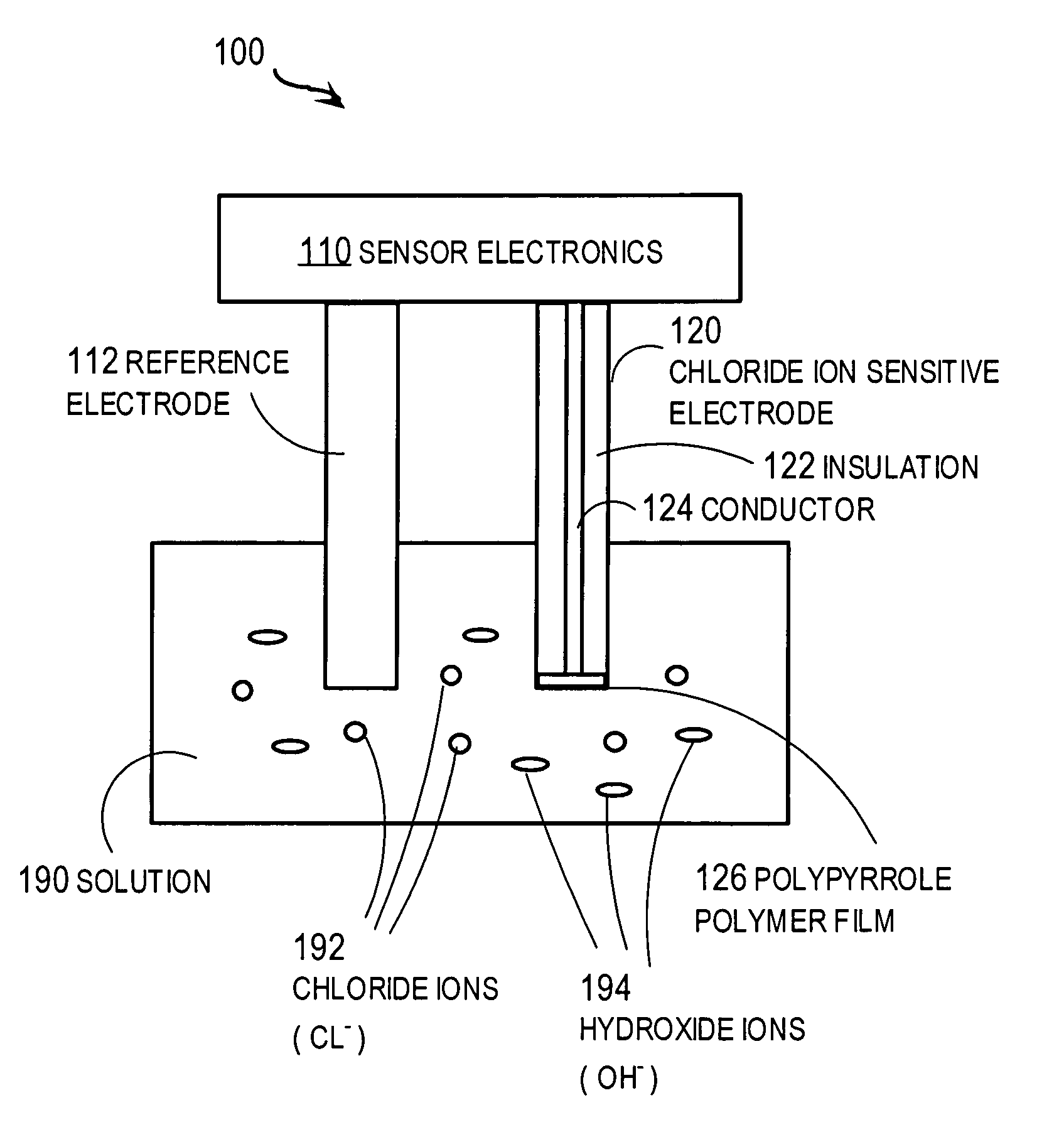
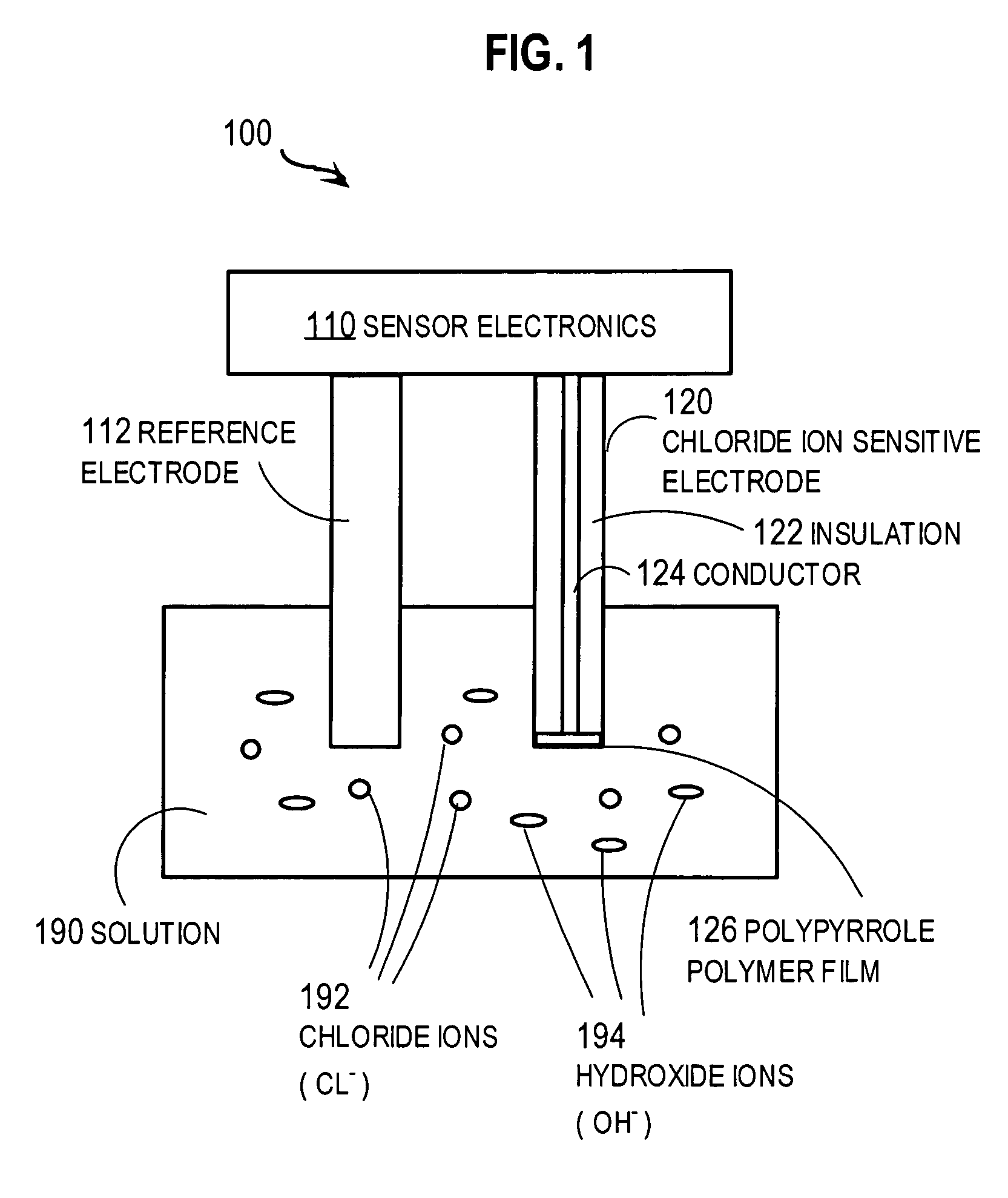
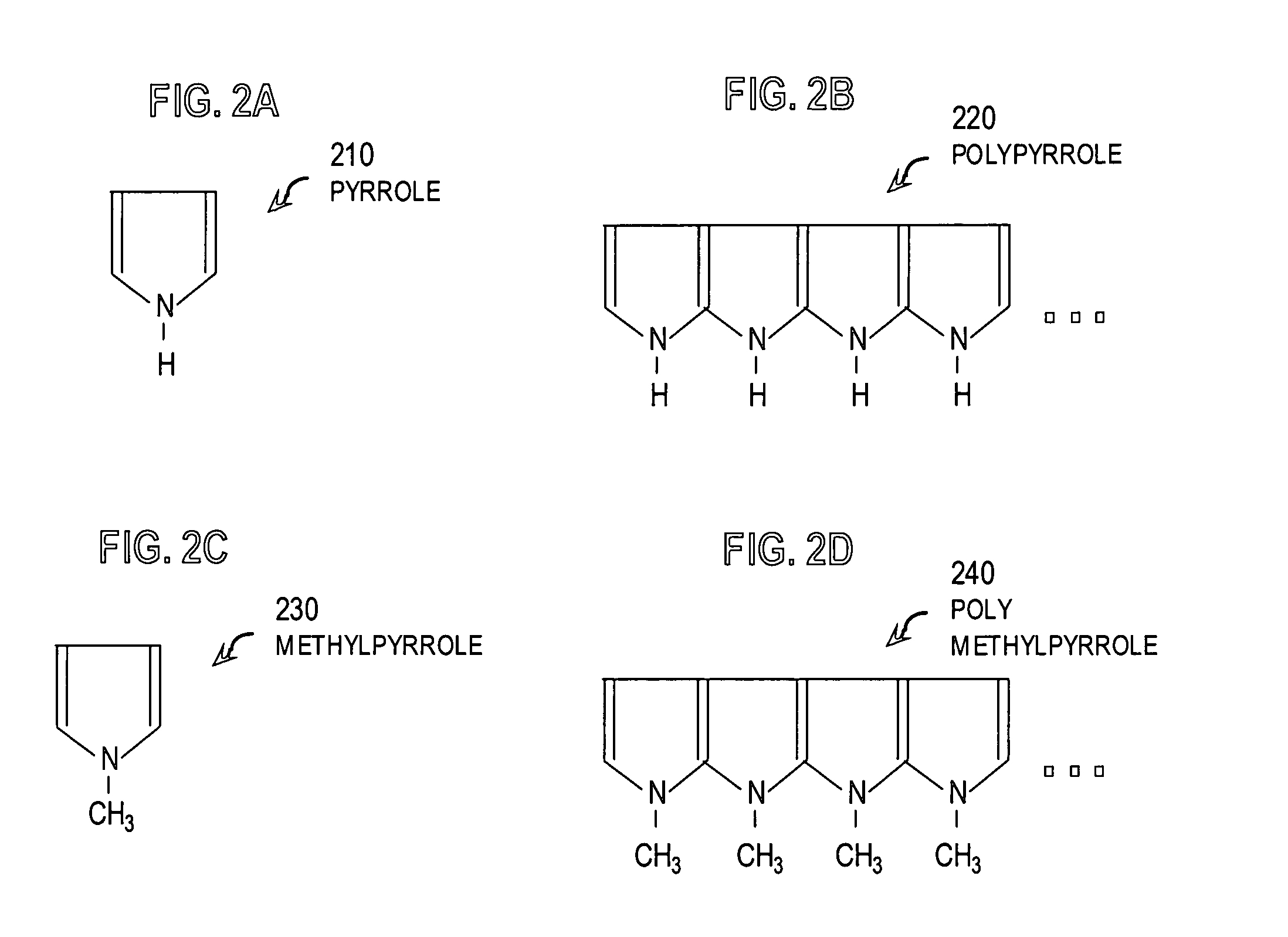
  • Techniques for sensing chloride ions in wet or dry media
  • Techniques for sensing chloride ions in wet or dry media
  • Techniques for sensing chloride ions in wet or dry media

Examples


Embodiment Construction

[0039]Techniques are described for measuring chloride ions in a medium. In the following description, for the purposes of explanation, numerous specific details are set forth in order to provide a thorough understanding of the present invention. It will be apparent, however, to one skilled in the art that the present invention may be practiced without these specific details. In other instances, well-known structures and devices are shown in block diagram form in order to avoid unnecessarily obscuring the present invention.

[0040]Particular embodiments of the invention are described in the context of measuring chloride ions in reinforced concrete decks of structures such as bridges and piers. However, the invention is not limited to this context, and embodiments may be deployed to measure chloride ion concentrations in solutions, in gases such as air, and at other solid media, such as in non-reinforced concrete or on steel girders.

[0041]In the concrete context, it is desirable that th...


PUM

PropertyMeasurementUnit
pHaaaaaaaaaa
concentrationaaaaaaaaaa
surface areaaaaaaaaaaa

Abstract

Techniques are provided for measuring chloride ion concentration in a medium. The techniques allow measurements to be made in dry or alkaline media, or both. For alkaline conditions, a sensor includes a pair of electrodes and a polymer film imprinted for uptake of chloride ions under alkaline conditions. The film is deposited to be in contact with at least one electrode and the medium. For dry conditions, a sensor includes a pair of electrodes and a conductive polymer film imprinted for uptake of chloride ions. The film is in contact with the pair of electrodes, and is positioned for contact with the medium. An electrical conductivity of the film depends on an amount of chloride ions taken up by the film. Some techniques allow chloride ion measurements over years at sensors embedded in concrete. Such measurements allow the determination of the progress of rebar corrosion in concrete infrastructure.

Description

CROSS-REFERENCE TO RELATED APPLICATIONS[0001]This application claims benefit of Provisional Application 60 / 432,520, filed Dec. 11, 2002, under 35 U.S.C. §119(e).BACKGROUND OF THE INVENTION[0002]1. Field of the Invention[0003]The present invention relates to a sensor, an apparatus incorporating the sensor and a method of fabricating the sensor to measure chloride ions; and in particular to measuring chloride ions in difficult conditions, such as varying wet and dry conditions in structural concrete with high pH for a duration of years.[0004]2. Description of the Related Art[0005]The United States is replacing aging infrastructure (such as buildings, bridges and piers) and simultaneously developing the tools and techniques to monitor new infrastructure as it ages. In particular, the US Department of Transportation and other organizations are developing approaches to monitor these structures in order to manage their maintenance and rehabilitation.[0006]Currently, trained personnel base...

Claims


Application Information

Patent Timeline
Patent Type & Authority Patents(United States)
IPC IPC(8): G01N27/333
CPCG01N27/3335
Inventor MURRAY, GEORGE M.CAIN, RUSSELL P.CARKHUFF, BLISS G.WEISKOPF, FRANCIS
Owner THE JOHN HOPKINS UNIV SCHOOL OF MEDICINE
Learn More