Electrical connection for a resistor element made of electrically-conductive fibers

a technology of resistor elements and electrical connections, which is applied in the direction of resistors, non-adjustable resistors, heater elements, etc., can solve the problems of reducing the performance of resistor elements, presenting characteristics that are poorly compatible with industrial manufacturing requirements, and a risk of leading to significant defects in molding, so as to reduce the cost and cycle time required for manufacturing blades.

Active Publication Date: 2006-06-20
EUROCOPTER
View PDF5 Cites 3 Cited by
  • Summary
  • Abstract
  • Description
  • Claims
  • Application Information

AI Technical Summary

Benefits of technology

[0014]An object of the present invention is to overcome the above-described limitations so as to enable industrialization to be undertaken in good conditions.

Problems solved by technology

This ice deposit weighs down the aircraft, sometimes to a very considerable extent, and also spoils the air flow by changing the shape of the aerodynamic surface, thus greatly degrades its performance.
One of the difficult points with that technology lies with feeding the resistor element with electricity, and more particularly lies with the connection between at least one end of said resistor element and one or more electrical power supply wires coming from the aircraft.
Although that connection device gives satisfaction, it nevertheless presents characteristics that are poorly compatible with the requirements of industrial manufacturing.
Firstly, it requires the electrical power supply wire(s) to be connected to the resistor element at the time the heater mat is being made.
The electrical power supply wires are difficult to incorporate in the blade mold and they run the risk of leading to significant defects in molding.
The cycle time and manufacturing cost of the blade are then increased in penalizing manner.
Secondly, the high degree of flexibility and deformability of the tubular sheath lead to implementation difficulties, particularly for holding the assembly comprising the tubular sheath and the electrical power supply wire in position on the resistor element while the heater mat is being draped.
Furthermore, the molding pressure exerted during polymerization of the heater mat can lead to misalignments and deformations of the electrical connections.
These defects lead to poor quality electrical contact that can lead to abnormal levels of local heating.
This resistance thus greatly limits the magnitude of electric current that can be delivered to the resistor element.
At the current levels required for good operation of the heater mat, this resistance can lead to excessive heating of the electrical connection zone.
Nevertheless, that type of connection leads to considerable extra thickness in the electrical connection zone.
Under such conditions, the aerodynamic surfaces need to be specially arranged inside the volume they define in order to be able to receive the device, and sometimes that can make it impossible to integrate the device on already-existing aerodynamic surfaces.
That operation is difficult and often leads to a surface that is not very uniform.
Even when performed by experienced operators, manufacturing time is long and the final result is poorly reproducible, which naturally is not compatible with satisfactory industrialization of the device.

Method used


Image

  • Electrical connection for a resistor element made of electrically-conductive fibers
  • Electrical connection for a resistor element made of electrically-conductive fibers

Examples


Embodiment Construction

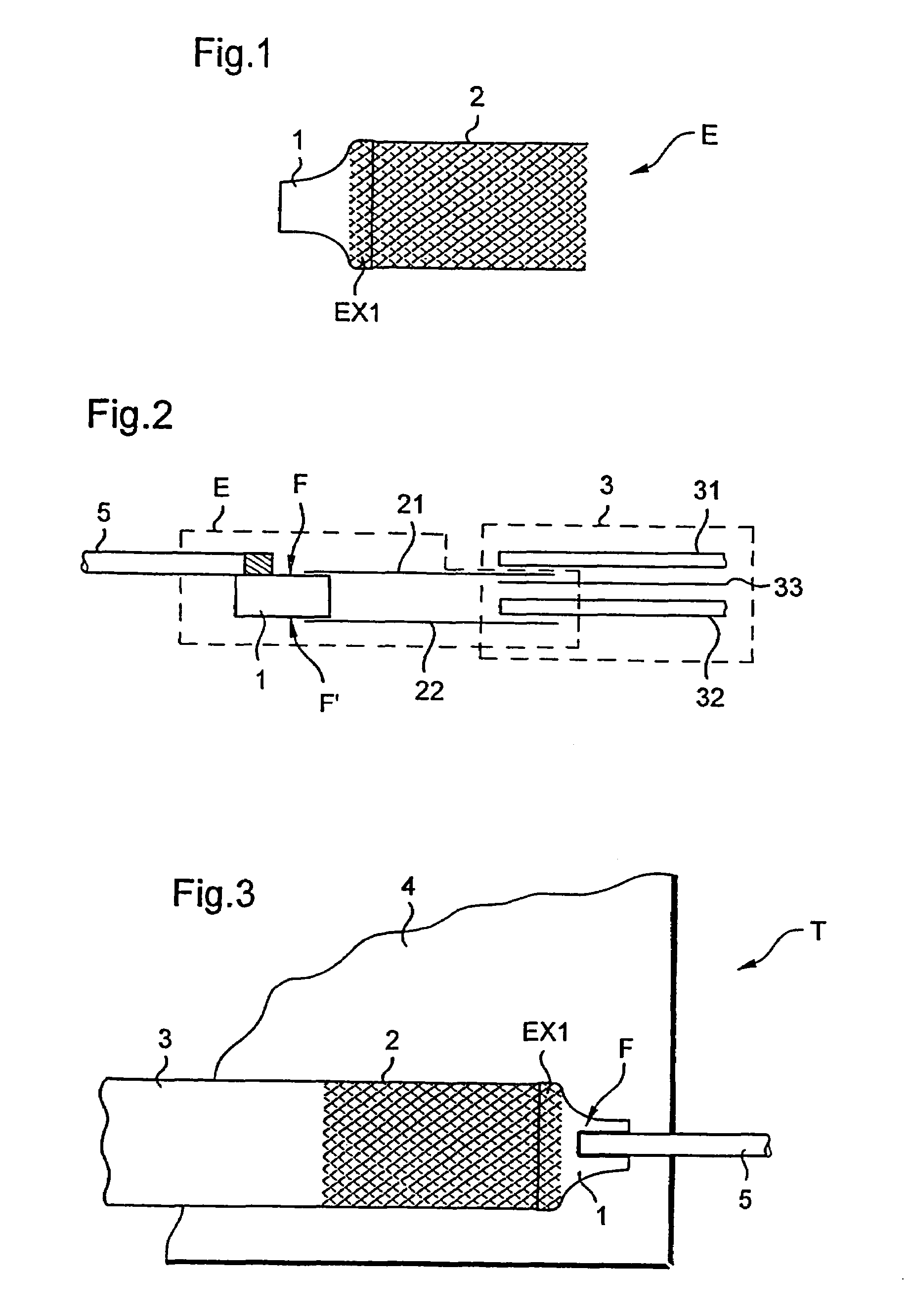
[0034]Elements that are present in more than one figure are given the same reference in all of them.

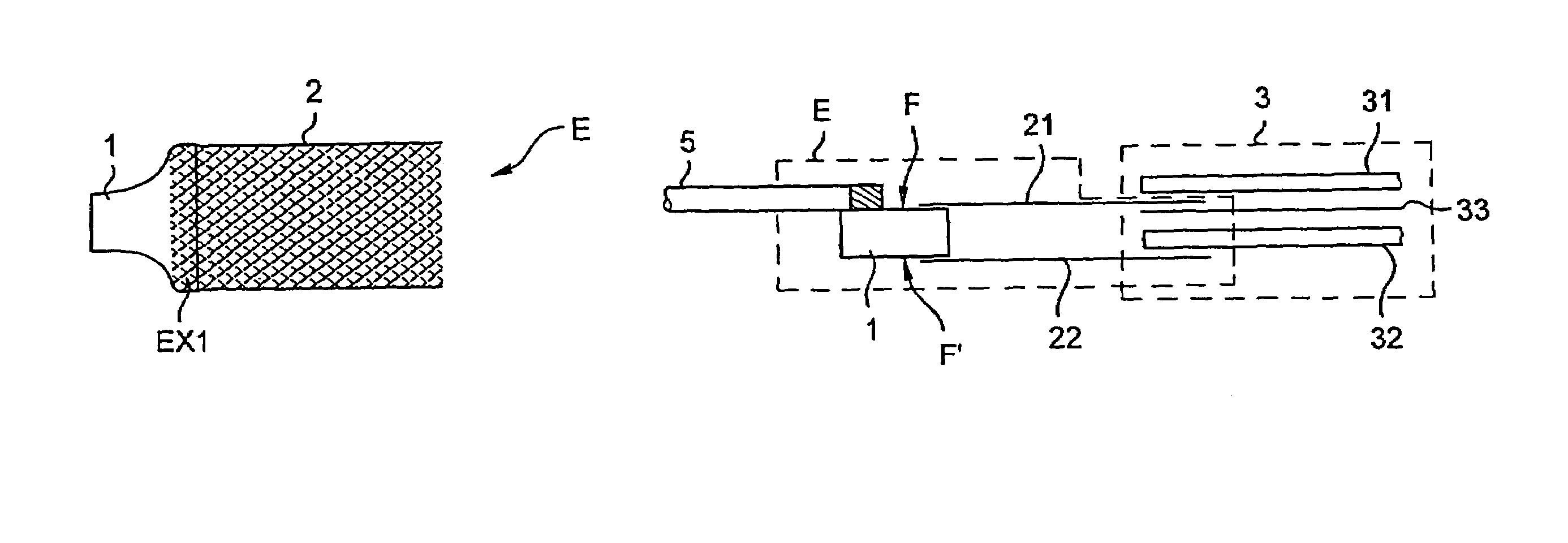
[0035]FIG. 1 shows a connection endpiece E of the invention for providing an electrical connection between a resistor element and an electrical power supply wire.

[0036]The endpiece E comprises a rigid metal connector member 2 of substantially flat shape arranged at a first zone EX1 of a metal plate 1.

[0037]Depending on the desired current, the connector member can be provided in four variants.

[0038]In a first variant, the connector member comprises an expanded metal element, and in a second variant it comprises a previously punched metal sheet. A third variant consists in using a metal fabric woven to constitute the connector member.

[0039]Finally, in a fourth variant, the connector member is obtained from a metal element that has been subjected to chemical machining so as to present roughnesses or crevasses in / or its face that is to come into contact with a resistor element.

[0040]FIG....


PUM


Abstract

A connection endpiece placed on a resistor element provided with at least one layer of electrically-conductive fibers, the endpiece serving to connect a power supply wire electrically to the resistor element. The endpiece includes at least one metal plate having a top face for connection to the power supply wire, and provided with at least one rigid metal connector member of substantially flat shape arranged at a first end of the metal plate and connected to at least one layer of electrically-conductive fibers of the resistor element, the top face of the metal plate being covered in a removable anti-adhesive covering.

Description

[0001]The present invention relates to an electrical connection device for a resistor element made of electrically-conductive fibers. This type of resistor element is used in particular for making heater mats of composite materials for de-icing aerodynamic surfaces of an aircraft.BACKGROUND OF THE INVENTION[0002]The problem of aerodynamic surfaces becoming iced is well known in the aviation industry. The term “icing” is used to designate more or less rapid formation of a deposit of ice on certain portions of an aircraft (leading edges of blades, propellers, wings, tail stabilizers and fins, windscreens, etc.). This ice forms in flight because an aerodynamic surface encounters droplets of water in the atmosphere that are supercooled. This supercooled state is a very precarious equilibrium state that can be broken by supplying a very small quantity of energy to the water droplet, e.g. in the form of a mechanical shock. The water then changes state and passes to the solid state. Thus, ...

Claims


Application Information

Patent Timeline
Patent Type & Authority Patents(United States)
IPC IPC(8): H05B3/08B64D15/12H01R4/00H01R43/00H05B3/06
CPCB64D15/12H05B3/06H01R43/00H01R4/00
Inventor BRUNNER, DANIELAMARI, ANDRE
Owner EUROCOPTER
Why Eureka
Try Eureka