Power generator system

Active Publication Date: 2006-06-20
YAMAHA MOTOR POWER PROD KK
View PDF11 Cites 25 Cited by
  • Summary
  • Abstract
  • Description
  • Claims
  • Application Information

AI Technical Summary

Benefits of technology

[0009]Features of the present invention improve the power generator

Problems solved by technology

Heat produced by the engine and the generator warms the air within the housing, which can reduce the generator's performance.
Relatively high temperatures within the housing can affect the operations of the engine and the generator.
Particularly, the efficiency for generating power can deteriorate as the internal resistances of the components increase with increased tempera

Method used


Image

  • Power generator system
  • Power generator system
  • Power generator system

Examples


Example

Overall Structure of Engine-Driven Generator

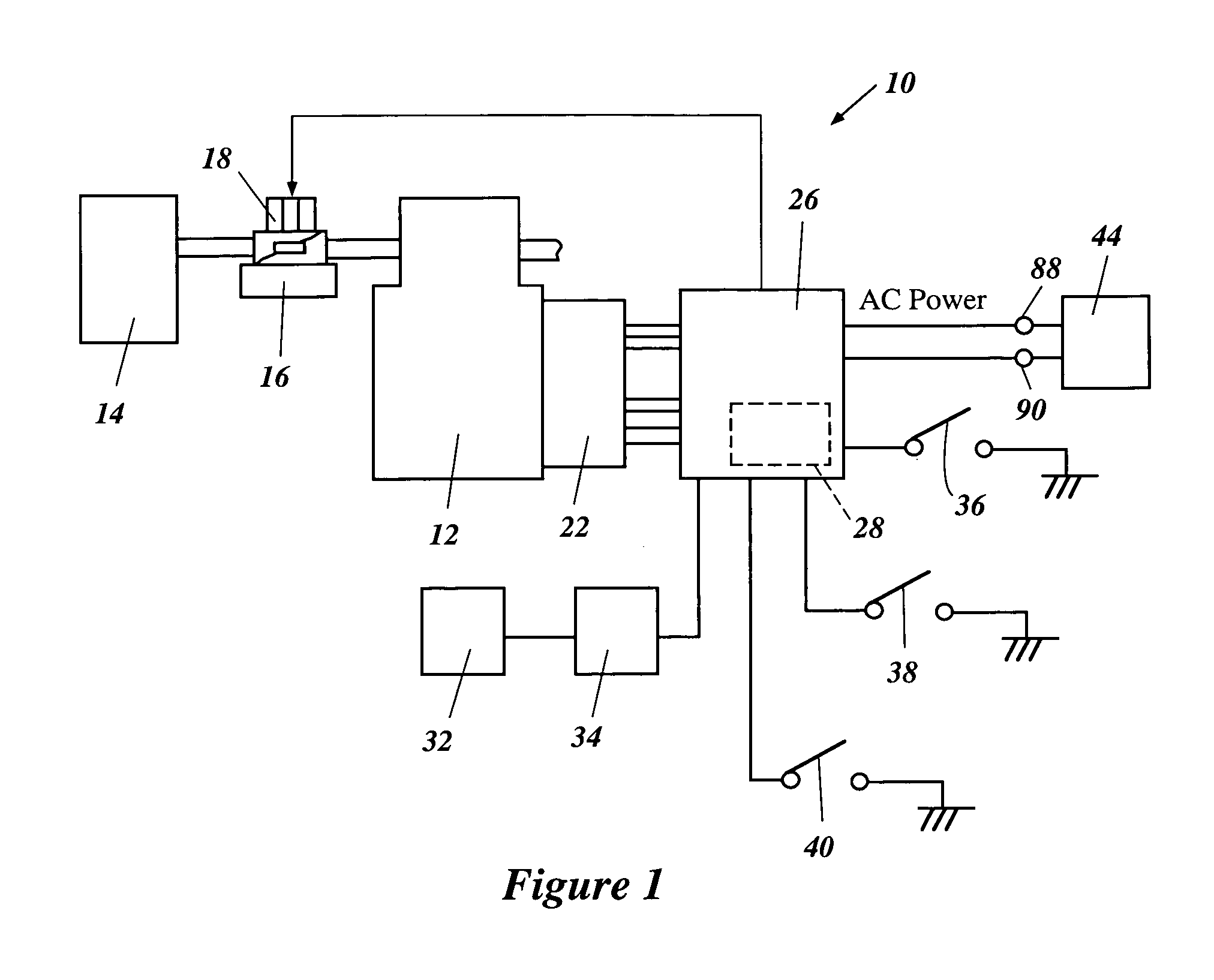
[0041]An overall structure of an engine-driven generator 10 that can be used with various features, aspects and advantages of the present invention is illustrated in FIG. 1. The illustrated engine-driven generator 10 generally comprises an internal combustion engine 12. The engine 12 can comprise one or more cylinders that form combustion chambers. The combustion chambers and cylinders may have any orientation (e.g., in-line, V configuration, opposed, vertical or horizontal). The engine 12 can operate in accordance with any combustion principle (e.g., four-cycle, two-cycle, rotary, or the like).

[0042]The engine 12 preferably comprises an air intake system, a fuel supply system, an ignition system and an exhaust system. A plenum chamber 14 draws air into the intake system. The plenum chamber 14 advantageously smoothes the air and reduces intake noise. A carburetor 16 is included as a portion of the intake system and as a portion of the fuel...


PUM


Abstract

A power generator system incorporates a generator driven by an engine. A case houses the generator and the engine. A controller communicates with the engine so as to control the speed at which the engine drives the generator. A temperature sensor is disposed so as to sense a temperature within the case and to send a temperature signal to the controller. The controller controls the speed of the engine depending upon at least the temperature signal received from the temperature sensor.

Description

RELATED APPLICATIONS[0001]The present application is based on and claims priority under 35 U.S.C. § 119 to Japanese Patent Application No. 2002-118763 filed on Apr. 22, 2002, and is also based on Japanese Patent Application No. 2002-078944 filed on Mar. 20, 2002, Japanese Patent Application No. 2002-086027 filed on Mar. 26, 2002, and Japanese Patent Application No. 2002-094655 filed on Mar. 29, 2002, the disclosures of which are all hereby incorporated by reference in their entirety.BACKGROUND OF THE INVENTION[0002]1. Field of the Invention[0003]The present invention generally relates to a power generator system and, in particular, to an improved power generator system incorporating a generator driven by a prime mover that operates at controlled speeds.[0004]2. Description of the Related Art[0005]Portable power supplies, such as electrical power generator systems that incorporate a generator driven by an engine, are popular for many uses. In an exemplary portable power supply disclo...

Claims


Application Information

Patent Timeline
IPC IPC(8): F02B63/00F02B63/04F02D9/02F02D13/04F02D29/06F02D41/04F02D45/00H02P9/04
CPCF02B63/04H02P9/04F02D29/06F02D13/04H02M1/0085
Inventor FUKAYA, MITSUOUCHINO, TAKASHISUGIYAMA, TAKAHIDE
Owner YAMAHA MOTOR POWER PROD KK
Why Eureka
Try Eureka