Apparatus, system and method of calibrating medical imaging systems

a technology of medical imaging and apparatus, applied in the field of medical imaging systems, can solve the problems of radial and rotational distortion of image produced by image intensifier, initial image generation exhibit distortion, and one source of distortion is gravity, so as to achieve strong clinical benefit and increase the effect of spa

Inactive Publication Date: 2006-06-20
IBM CORP
View PDF14 Cites 73 Cited by
  • Summary
  • Abstract
  • Description
  • Claims
  • Application Information

AI Technical Summary

Benefits of technology

[0027]When the projection grid is removed, more space between the image intensifier and the X-ray source is created in which to fit the patient, and to perform surgical procedure, which is a strong clinical benefit. Removal of both calibration plates would not only increase the space between we image intensifier and the X-ray source, but would also result in an image unobscured by the radio-opaque beads on the calibration plates.

Problems solved by technology

However, initial images generated exhibit distortion due to a number of sources.
One source of distortion is gravity.
Such deformations vary with changes in the orientation of the C-arm, resulting in radial and rotational distortions of the image produced by the image intensifier.
Another source of distortion is the Earth's magnetic field.
The presence of fiducial beads in the image also degrades the image quality.
The main disadvantage associated with the use of a single dewarp grid, is the lack of information relating to C-arm deformation due to gravity-induced bending.
A limitation associated with this method is that the suspended body must not move throughout the surgical procedure.
If the suspended body or the positioning sensor moves, the calibration process needs to be repeated, which may cause some difficulty if calibration is required during a surgical procedure.
Another limitation is that the sensor must be placed so that it can be men which is cumbersome during surgery.
Limitations associated with this method include the necessity of encoding, of position sensors, the complexity of calibrating encoders and optical position sensors and the assumption that the position sensor base is oriented consistently with gravity.
Further, this method requires a dewarp grid.
Without a dewarp grid, there is insufficient information to compute and correct for magnetic field induced distortions in the image.

Method used


Image

  • Apparatus, system and method of calibrating medical imaging systems
  • Apparatus, system and method of calibrating medical imaging systems
  • Apparatus, system and method of calibrating medical imaging systems

Examples


Embodiment Construction

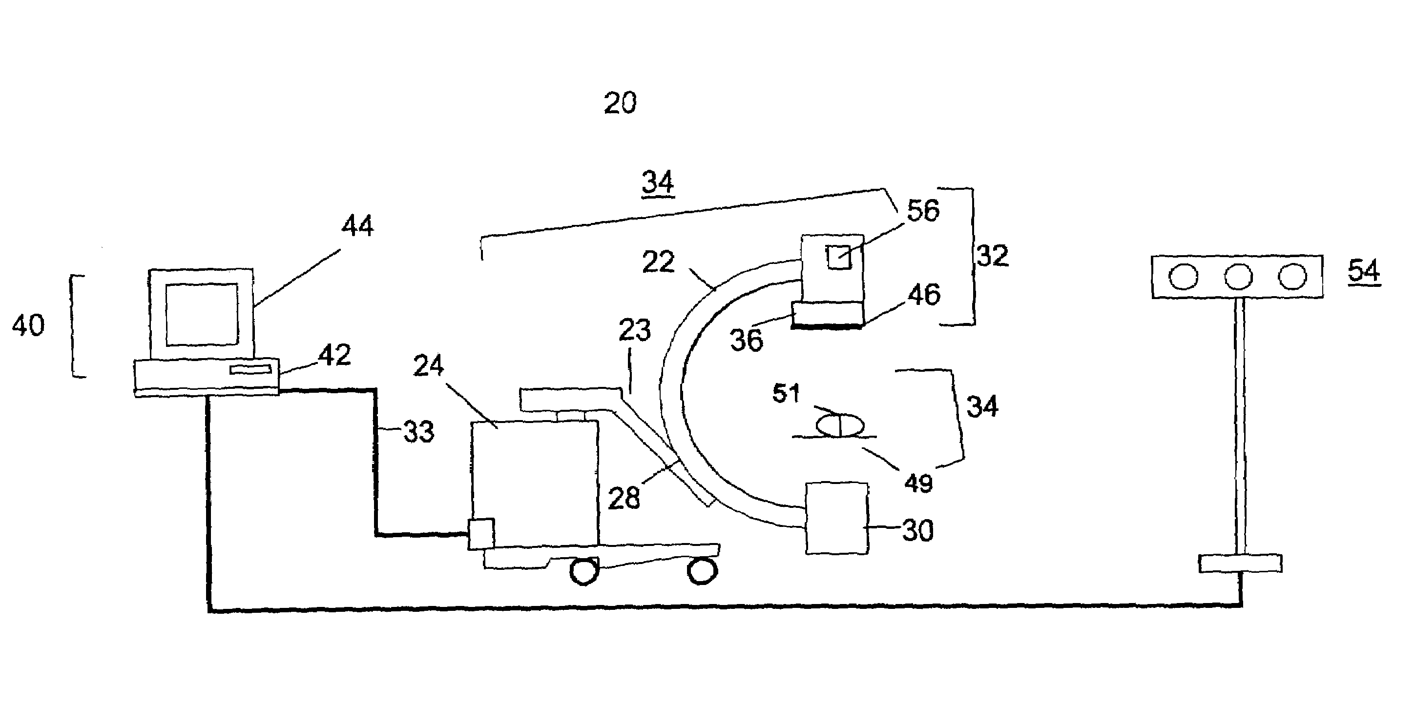
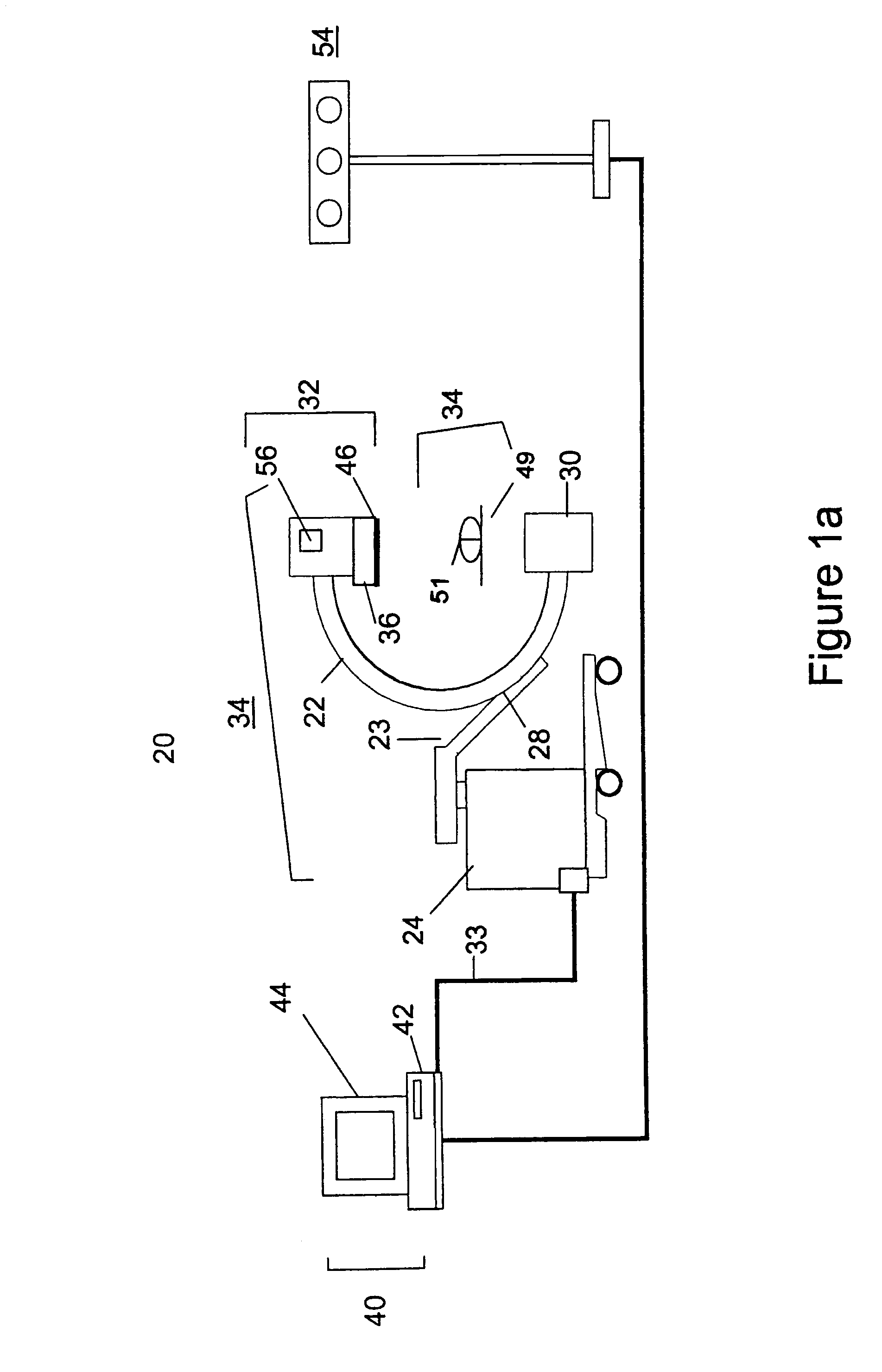
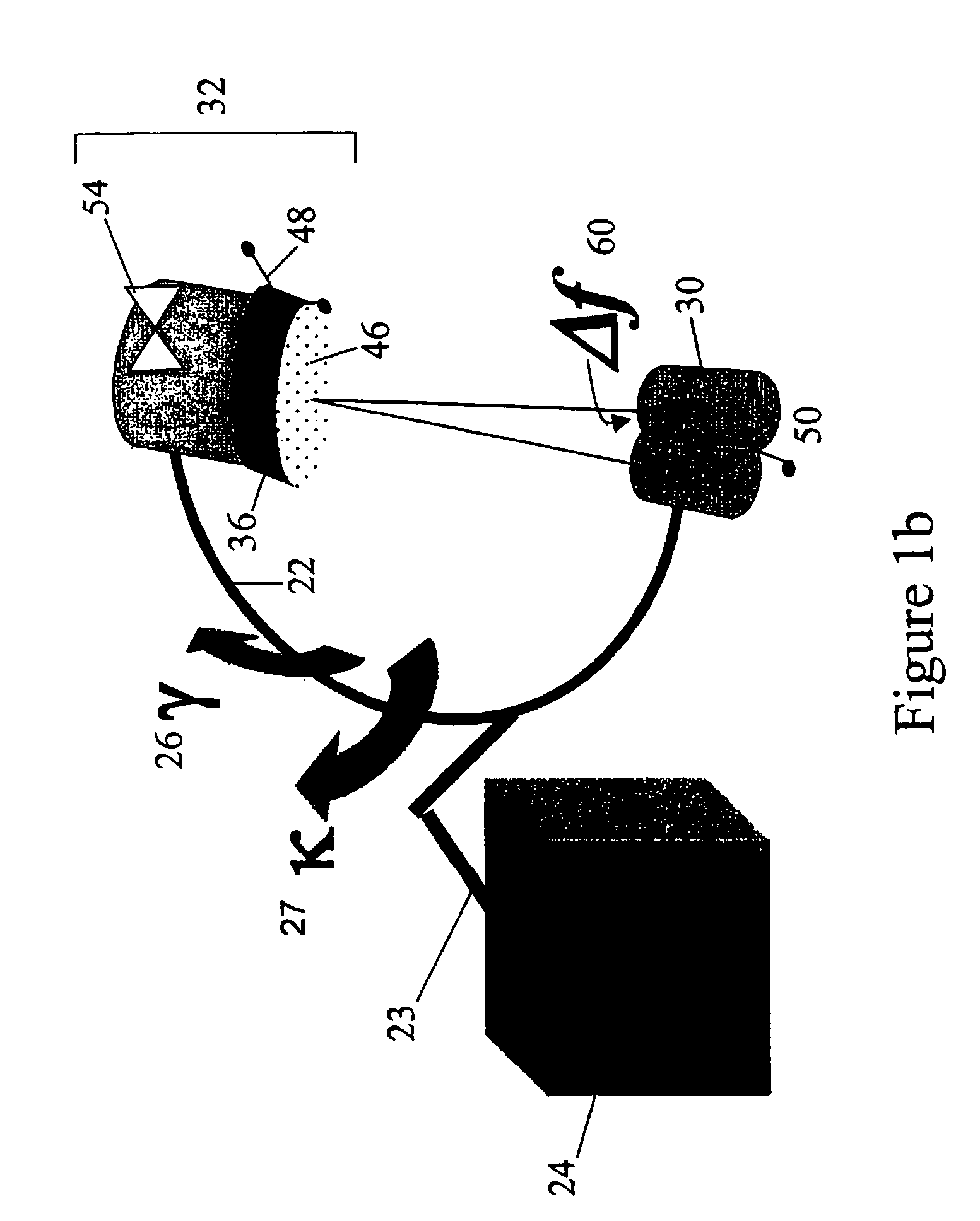
[0034]Referring to FIGS. 1a and 1b, a fluoroscopic C-arm X-ray imaging apparatus is provided. Imaging device 20 includes a C-arm 22 slidably and pivotally attached to a downwardly extending L-arm 23 at an attachment point 28. The L-arm 23 is held in suspension by a support base 24. The C-arm 22 is orbitable γ degrees about an axis of orbital rotation 27, while the L-arm 23 is rotatable κ degrees about an axis of lateral rotation 27 to thereby rotate the C-arm 22 laterally. The imaging device 20 may electronically communicate with a control unit (not shown) such that the control unit through external input may operate the degree of orbital and lateral rotation of the imaging device 20. The degrees of rotation γ and κ may be displayed for orientation.

[0035]An imaging source 30 is located at one end of C-arm 22 and imaging receptor 32 is located at the other end of C-arm 22. In the embodiment depicted in FIGS. 1a and 1b, the imaging source 30 is an X-ray source while the imaging recept...


PUM


Abstract

A C-arm imaging device method, apparatus and system are provided. The apparatus and system includes a module for determining the positions of an imaging source and an imaging receptor and a local gravity vector to determine an imaging source focal point displacement. The apparatus and system may include a module for determining magnetic field distortion. Data obtained by the apparatus and system can be stored for use in subsequent interpolation of imaging source focal point displacement for the C-arm imaging device.

Description

FIELD OF THE INVENTION[0001]The present invention relates to medical imaging systems, and is particularly concerned with an apparatus, system and method for calibrating medical imaging systems used in computer-assisted surgery.BACKGROUND OF THE INVENTION[0002]Minimally invasive, surgical techniques are becoming more prevalent as a means to reduce injury to the patient during surgical procedures, and thereby improving patient recovery to this ted, computer assisted surgical (CAS) techniques are being employed more frequently.[0003]In conventional CAS, surgeons employ computational and image processing technologies to assist in surgical procedure. High resolution, three-dimensional internal images of a patient are taken prior to surgery, for example, computerized tomograph (CT) or magnetic resonance imaging (MRI). The images are digitized, processed and saved in a computer system for use in a variety of purposes. In this specification, CAS includes surgical planning, surgical navigati...

Claims


Application Information

Patent Timeline
Patent Type & Authority Patents(United States)
IPC IPC(8): A61B5/05A61B6/00
CPCA61B6/08A61B6/4405A61B6/547A61B6/583A61B6/4441A61B6/4291
Inventor SATI, MARWANCYR, MARTIN
Owner IBM CORP
Why Eureka
Try Eureka