Method for making speed reducers

a technology of speed reducers and gear reductions, applied in the direction of gears, gear lubrication/cooling, gearing elements, etc., can solve the problems of not being able to perform lifting functions, gears are not the only suitable means for lifting functions, and generally self-locking, etc., to achieve quiet and smooth operation

Inactive Publication Date: 2006-06-27
GIBSON SANDRA E
View PDF6 Cites 7 Cited by
  • Summary
  • Abstract
  • Description
  • Claims
  • Application Information

AI Technical Summary

Benefits of technology

[0052]A closely related object is to provide...

Problems solved by technology

Nor are gears the only suitable means for performing lifting functions.
However, in most applications a gear train is less expensive and usually more practical than such alternatives.
When properly designed and installed for a particular application, they are generally self-locking when the load is at rest.
For example, spur gears exhibit little or no resistan...

Method used


Image

  • Method for making speed reducers
  • Method for making speed reducers
  • Method for making speed reducers

Examples


Embodiment Construction

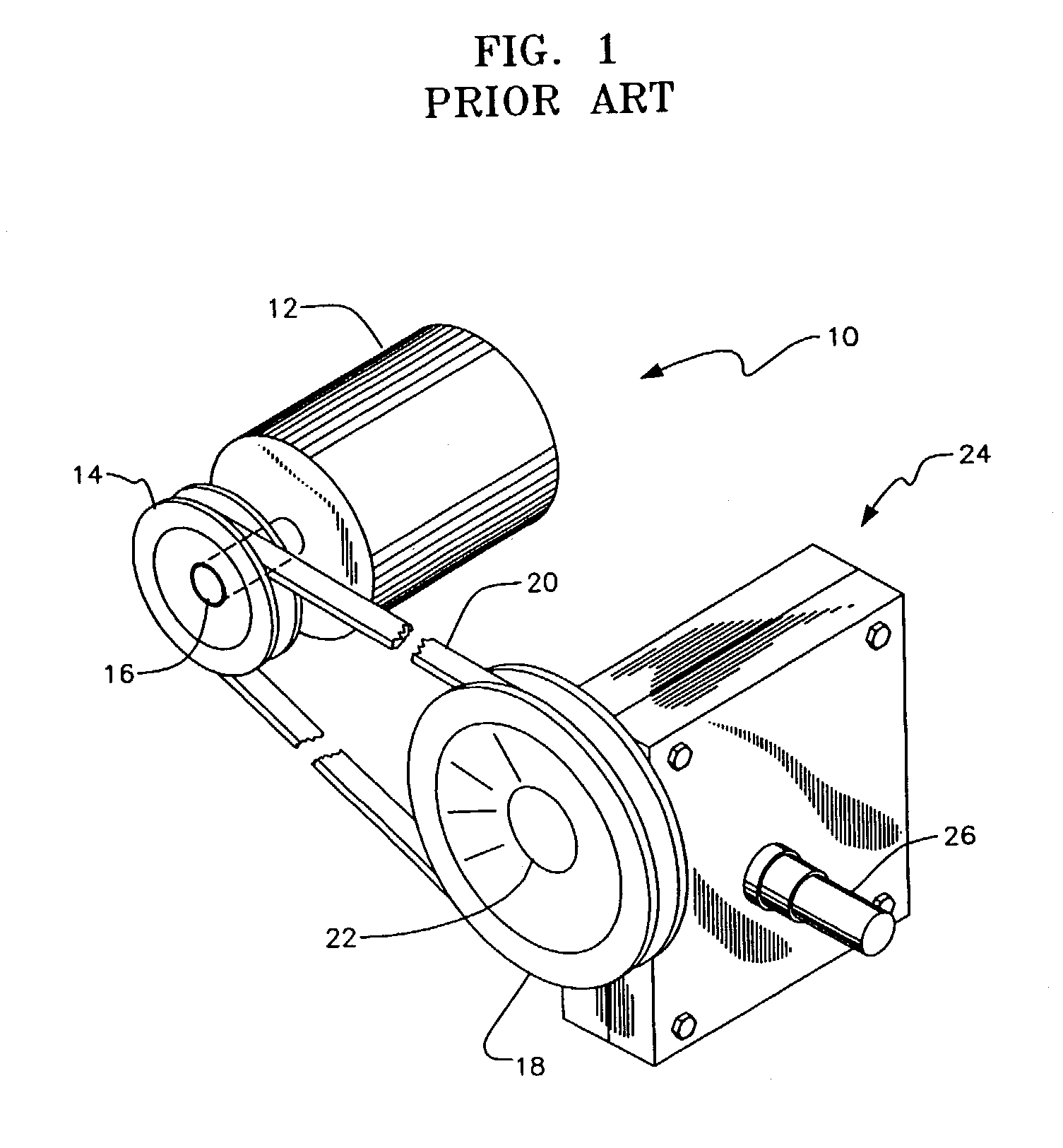
[0076]Referring now to FIG. 1, it will there be seen that a prior art speed reducer assembly of the belt and pulley type is denoted as a whole by the reference numeral 10. Assembly 10 includes motor 12, first pulley 14 mounted on output shaft 16 of said motor, second pulley 18, belt 20 interconnecting first pulley 14 and second pulley 18, pulley shaft 22 that rotates conjointly with second pulley 18, speed reducing gear housing 24 that houses a gear train, not shown, and a power take off shaft 26 that may be employed for many lifting purposes such as, but not limited to, boat lifting.

[0077]A safety cover, not shown, is commonly provided to cover belt 20 and pulleys 14, 18.

[0078]Speed reducer assemblies of this type have limited lifting capacity due to the slippage of belt 20 with respect to pulleys 14, 18. They also lack a self-locking feature and the lifted item may therefore gradually lower over time due to the phenomena of inertia-generated coasting. Moreover, power increases wit...


PUM


Abstract

A CNC machine makes a single speed reducer by forming a worm recess, a worm gear recess, and a worm shaft groove that is discontinuous at the worm recess in a first solid block of aluminum. Matching recesses and grooves are formed in a second solid block of aluminum in the same way so that a worm cavity, a worm gear cavity, and a worm shaft bore are formed when the two blocks are placed in juxtaposition to one another. The worm shaft bore enables the reducer to have two different mounting configurations. A double speed reducer made by the same techniques has even more mounting configurations. The design also minimizes gear lash, end play, and inertia generated coasting and accommodates power transmission systems other than gear trains.

Description

BACKGROUND OF INVENTION[0001]1. Field of the Invention[0002]This invention relates, generally, to speed reducers. More particularly, it relates to a method for making speed reducers from solid metallic blocks by CNC machining.[0003]2. Description of the Prior Art[0004]The conventional way to make a speed reducer is to cast the individual parts thereof in a mold. The parts that are individually cast include the housing and the gears or other power transmission means within the housing. The working parts of the speed reducer are assembled and the completed assembly is placed into the housing.[0005]The housing is typically a box-like structure that encloses the gear train or other power transmission system. The housing not only protects the parts therewithin from the elements, it also acts as a safety cover to protect individuals from sprocket gears, sprocket chains, and the like that may form a part of the speed reducer.[0006]Worms and worm gears are well-suited for use in speed reduc...

Claims


Application Information

Patent Timeline
IPC IPC(8): F16H1/16
CPCF16H1/16Y10T74/2186Y10T74/19828
Inventor GIBSON, RANDOLPH P.
Owner GIBSON SANDRA E
Why Eureka
Try Eureka