Online alternator flywheel system

a flywheel system and alternator technology, applied in the field of online alternator flywheel system, can solve the problem of increasing standby power, and achieve the effect of preventing power interruptions

Inactive Publication Date: 2006-06-27
GABRYS CHRISTOPHER W
View PDF20 Cites 12 Cited by
  • Summary
  • Abstract
  • Description
  • Claims
  • Application Information

AI Technical Summary

Benefits of technology

[0006]Accordingly, the invention provides an improved flywheel energy storage system for preventing power interruptions to a load from interruptions of primary power. The flywheel system simultaneously provides instantaneous power protection and a controllable output for extraction of more of the energy from the flywheel.

Problems solved by technology

The application of high current to the field coil during standby operation (when power is not interrupted) disadvantageously produces significantly increased standby power dissipation of the flywheel system and heat that must be removed.

Method used


Image

  • Online alternator flywheel system
  • Online alternator flywheel system
  • Online alternator flywheel system

Examples


Embodiment Construction

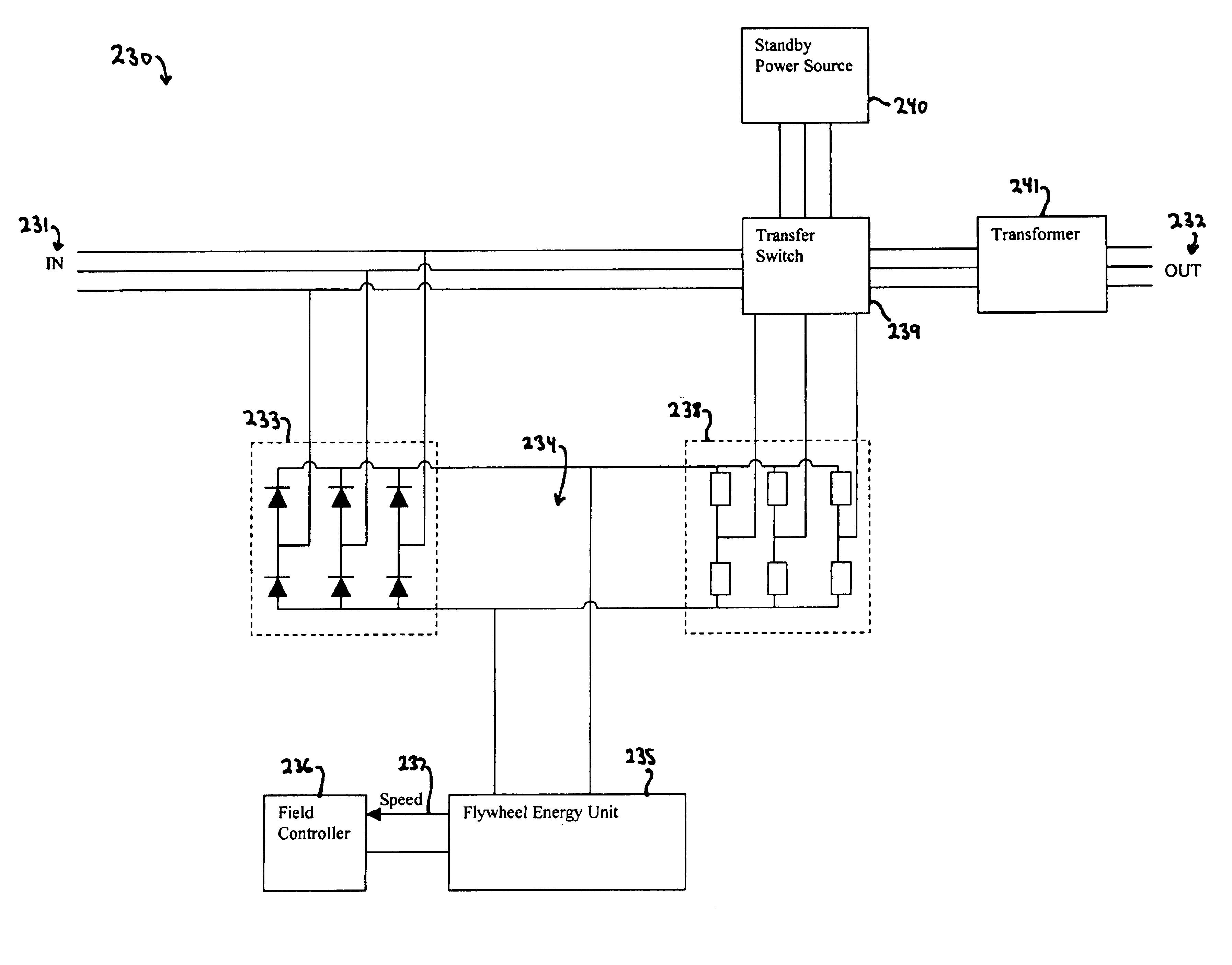
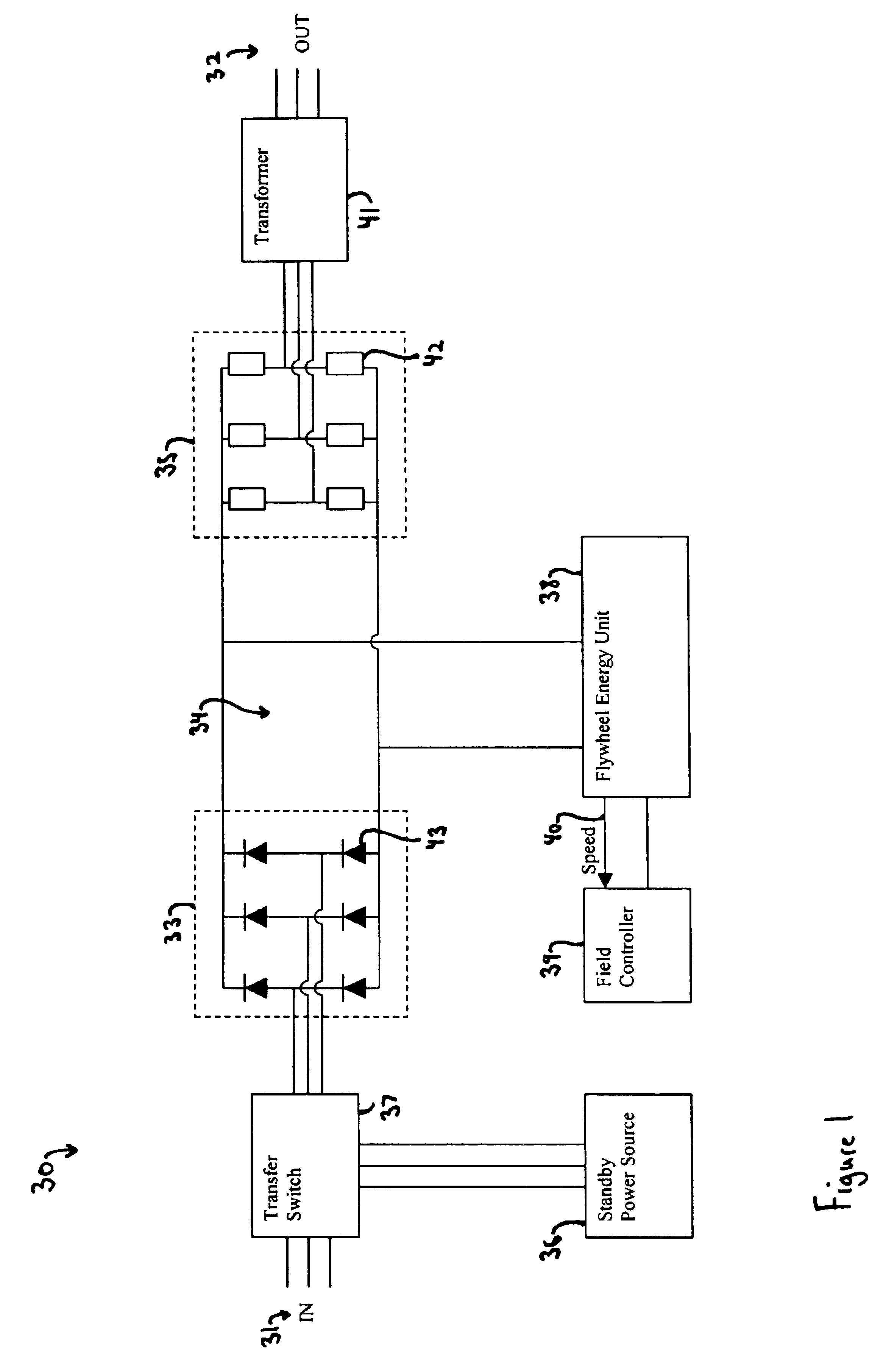
[0032]Turning to the drawings, wherein like reference characters designate identical or corresponding parts, and more particularly to FIG. 1 thereof, a power system 30 for supplying uninterrupted power is shown having a primary electrical power input 31 and an output 32 to a protected load. The input power 31 is rectified by a rectifier 33 and supplied to a DC buss 34. The rectifier 33 can be controlled or uncontrolled and constructed of diodes or thyristors 43. Power in the DC buss 34 is inverted through an inverter 35 and supplied to the power output 32. Capacitors, not shown, may also be connected across the DC buss 34 to smooth power by providing some capacitive energy storage. The inverter 35 is constructed with individual transistors 42 to convert the DC power to AC power as is known in the art. Although a 4-quadrant inverter can be utilized that can boost the flywheel voltage, the instantaneous full power capability of the invention allows for use of a much cheaper single qua...


PUM


Abstract

A flywheel energy storage system for preventing power interruptions to a load from interruptions of primary power includes a flywheel supported for rotation about an axis on a bearing system, and a motor-generator having a rotor coupled with the flywheel, and having a stator with multiple armature windings and a field coil. The field coil generates flux that passes through the armature windings as the rotor rotates to produce torque for accelerating the flywheel during charging, and produces electrical power from the flywheel during discharge. The armature windings are energized by a DC buss that is supplied by a rectifier connected to primary power. The flywheel system provides instantaneous full power capability along with output control for extracting more energy from the flywheel. The field coil is oversized and is powered in standby operation to produce an armature back emf that is at least 75% of the DC buss voltage. The current to the field coil remains substantially constant during a period including immediately before an interruption and immediately after and interruption of primary power. The flywheel system uniquely utilizes an extremely large field coil, which is preferably 25-50% of the weight of the flywheel. The increased field coil size allows for both full standby energization without overheating and also reduces the armature reaction such that full power is available during a power interruption without requiring instantaneous increasing of the field coil current. In one embodiment, the field controller has a speed sensor for monitoring rotational speed of the flywheel and for varying electrical power to the field coil, without monitoring the primary power for interruptions. The field controller varies electrical current to the field coil approximately inverse linearly with the rotational speed of the flywheel during both standby and discharging operation to govern power to the field coil during standby operation such that the back emf of the armature remains substantially constant during an interruption of power.

Description

[0001]This is related to U.S. Provisional Application No. 60 / 394,505 filed on Jul. 9, 2002 and entitled “Online Alternator Flywheel System”.[0002]This invention pertains to flywheel energy storage systems and more particularly to a flywheel system that is capable of providing instantaneous power protection in conjunction with a controllable output for increased energy extraction. The invention allows increased power protection while having less costly and complicated control and implementation.BACKGROUND OF THE INVENTION[0003]Flywheel energy storage systems have emerged as an alternative to electrochemical batteries for storing energy with many advantages including higher reliability, longer life, lower or no maintenance, higher power capability and environmental friendliness. Flywheel energy storage systems store energy in a rotating flywheel that is supported by a low friction bearing system inside a chamber. The chamber is usually evacuated to reduce losses from aerodynamic drag....

Claims


Application Information

Patent Timeline
Patent Type & Authority Patents(United States)
IPC IPC(8): H02K7/02H02J3/30
CPCH02K7/025H02K11/048Y02E60/16H02M7/00
Inventor GABRYS, CHRISTOPHER W
Owner GABRYS CHRISTOPHER W
Why Eureka
Try Eureka