Exposure head and exposure apparatus

a technology of exposure apparatus and head, which is applied in the field of exposure head, can solve the problems of large reduction of light usage efficiency and loss of light amount due to apertures, and achieve the effect of reducing optical efficiency

Inactive Publication Date: 2006-06-27
FUJIFILM HLDG CORP +1
View PDF4 Cites 11 Cited by
  • Summary
  • Abstract
  • Description
  • Claims
  • Application Information

AI Technical Summary

Benefits of technology

[0012]In consideration of the circumstances described above, a major object of the present invention is to provide an exposure head and exposure apparatus capable of adjusting a beam spot which exposes an exposure surface to a desired spot diameter and spot shape without causing the occurrence of stray light or a reduction in optical efficiency.

Problems solved by technology

However in a case in which such apertures are used, light amount losses due to the apertures increase in accordance with increases in a rate of contraction of the laser beams, and light usage efficiency is greatly reduced.

Method used


Image

  • Exposure head and exposure apparatus
  • Exposure head and exposure apparatus
  • Exposure head and exposure apparatus

Examples


first embodiment

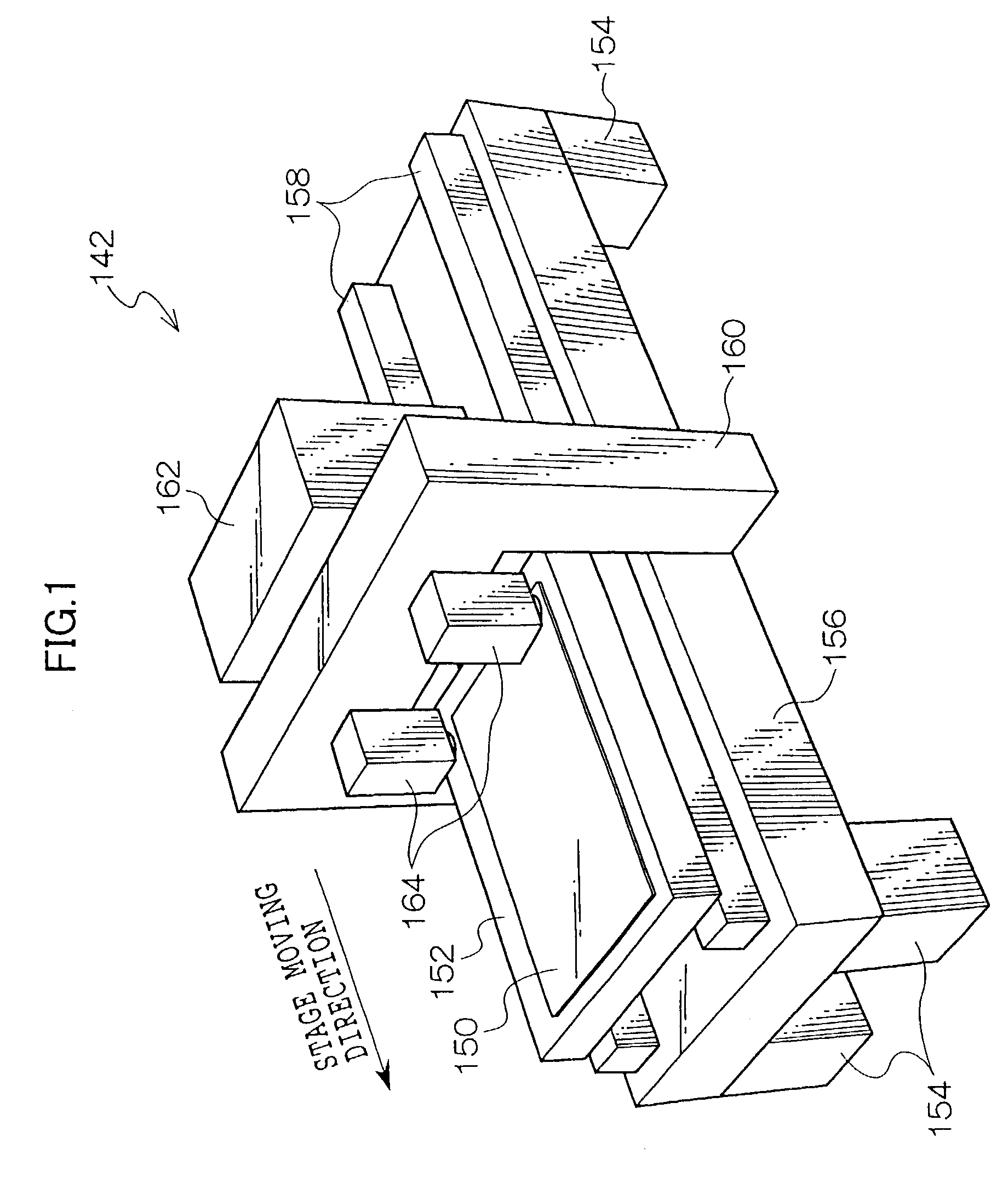
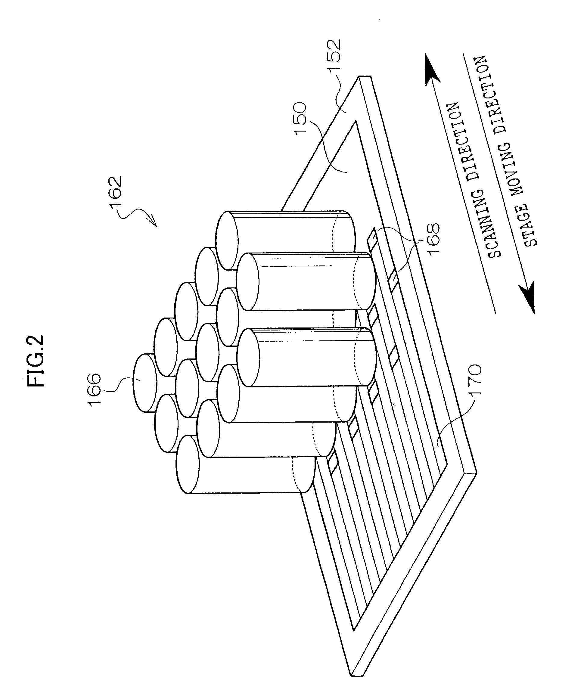
[0054]As shown in FIG. 1, an exposure apparatus 142 relating to a first embodiment of the present invention is provided with a flat board-form stage 152, which adsorbs and retains a sheet-form photosensitive material 150 at a surface thereof. Two guides 158, which extend in a stage movement direction, are provided at an upper face of a thick board-form equipment pedestal 156, which is supported at four leg portions 154. The stage 152 is disposed such that a longitudinal direction thereof is oriented in the stage movement direction, and is supported by the guides 158 so as to be reciprocally movable. At this exposure apparatus 142, an unillustrated driving apparatus is provided for driving the stage 152 along the guides 158.

[0055]At a central portion of the equipment pedestal 156, an ‘n’-like gate 160 is provided so as to straddle a movement path of the stage 152. Respective end portions of the gate 160 are fixed at two side faces of the equipment pedestal 156. Sandwiching the gate 1...

second embodiment

[0128]Herebelow, an exposure apparatus relating to a second embodiment of the present invention will be briefly described. In particular, portions that are different from the first embodiment described above will be detailed.

[0129]In the second embodiment, instead of the projecting optical system 146, an imaging optical system 146A is used.

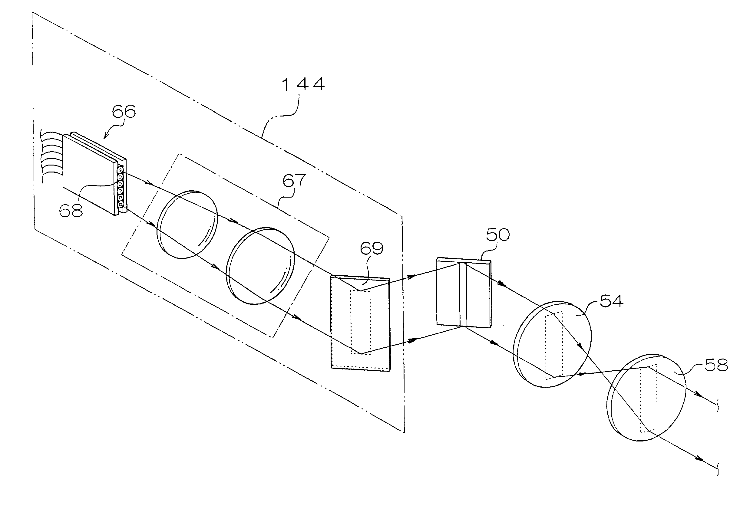
[0130]At the microfieldlens array 72, the plurality of first microlenses 74 are integrally formed in a one-to-one correspondence with the micromirrors 62 of the DMD 50 which reflect the light from the illumination unit 144. The first microlenses 74 are disposed at imaging surfaces of the micromirrors 62 on the optical axes of the laser beams which have been transmitted through the lens systems 54 and 58. The diameters of the first microlenses 74 are substantially the same as image sizes of real images of the micromirrors 62. At the microfieldlens array 72, the first microlenses 74 are arranged in two dimensions at a pitch the same as the size of t...


PUM

PropertyMeasurementUnit
reflectivityaaaaaaaaaa
angleaaaaaaaaaa
lengthaaaaaaaaaa

Abstract

A reduction in utilization efficiency of laser beams emitted from laser emission portions of illumination means is limited and an exposure surface is exposed by beam spots with desired spot diameters and spot forms. At an exposure head, first microlenses are arranged in a two dimensional manner so as to correspond to micromirrors at a DMD, and apertures are arranged in a two dimensional manner at back side focusing positions of the first microlenses. With this exposure head, light source images, which are formed to be very small at back side focusing positions of the first microlenses by the first microlenses, are projected onto the exposure surface, and these light source images serve as beam spots BS and expose the exposure surface.

Description

BACKGROUND OF THE INVENTION[0001]1. Field of the Invention[0002]The present invention relates to an exposure head for exposing an exposure surface at a recording medium or the like with a laser beam which is spatially modulated by a spatial modulation element in accordance with image data, and to an exposure apparatus equipped with this exposure head.[0003]2. Description of the Related Art[0004]Heretofore, various exposure apparatuses which employ spatial light modulation elements such as digital micromirror devices (DMD) and the like have been proposed for carrying out image exposure with light beams modulated in accordance with image data.[0005]An example of a DMD is a mirror device in which numerous micromirrors, which alter angles of reflection surfaces thereof in accordance with control signals, are arranged in a two-dimensional manner on a semiconductor support of silicon or the like. An example of an exposure apparatus which utilizes such a DMD is, as shown in FIG. 27, struct...

Claims


Application Information

Patent Timeline
Patent Type & Authority Patents(United States)
IPC IPC(8): G02B26/00G02B26/08G03F7/20
CPCG02B26/0841G03F7/70291G03F7/70275G03F7/7005
Inventor SUNAGAWA, HIROSHIISHIKAWA, HIROMIOKAZAKI, YOJINAGANO, KAZUHIKOFUJII, TAKESHIOMORI, TOSHIHIKO
Owner FUJIFILM HLDG CORP
Why Eureka
Try Eureka