Sheeting with composite image that floats

a composite image and image technology, applied in the field of sheeting, can solve the problems of unadaptable methods for producing three-dimensional images of virtual objects, image must be illuminated,

Inactive Publication Date: 2006-06-27
3M INNOVATIVE PROPERTIES CO
View PDF81 Cites 122 Cited by
  • Summary
  • Abstract
  • Description
  • Claims
  • Application Information

AI Technical Summary

Benefits of technology

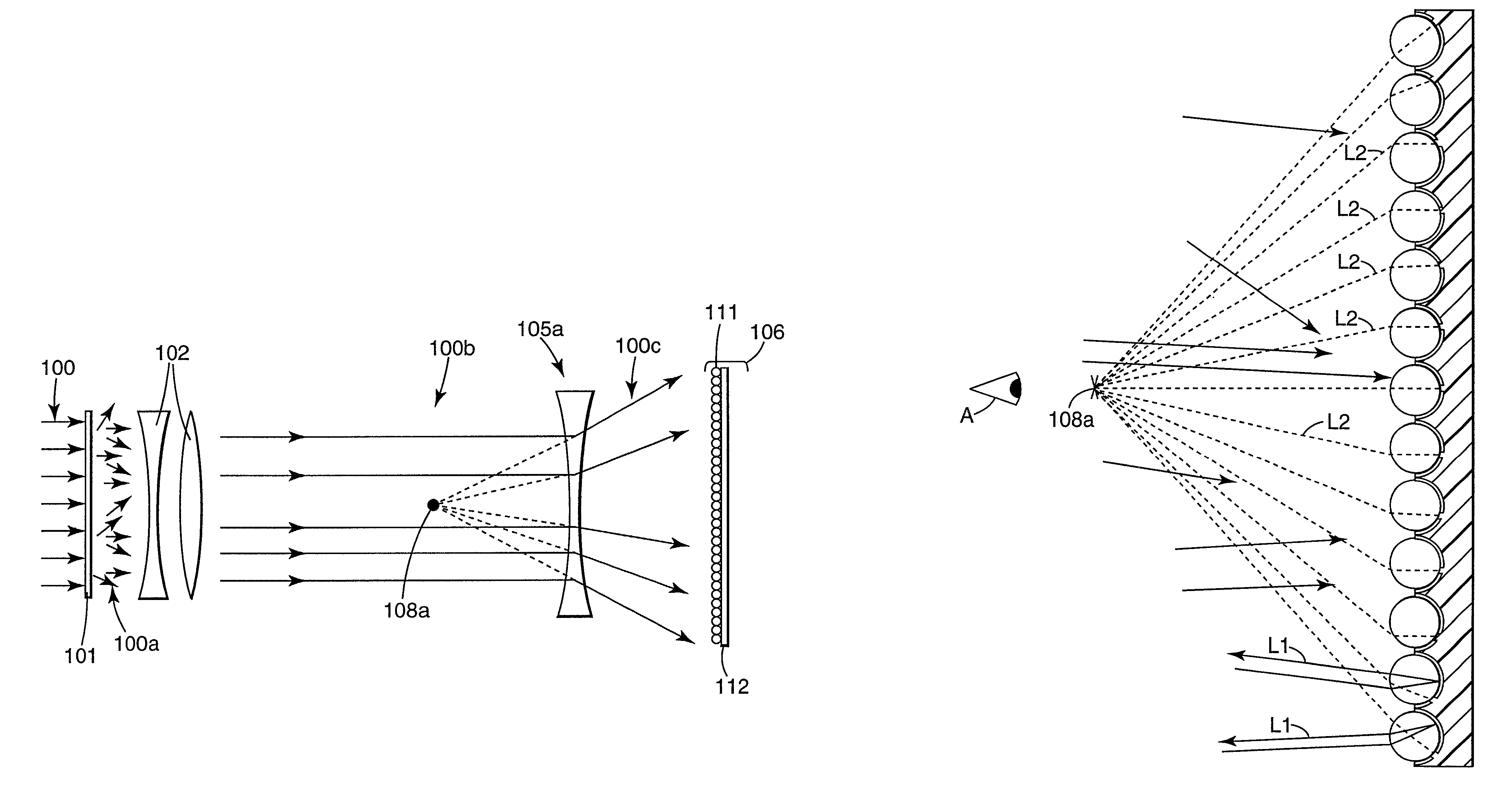
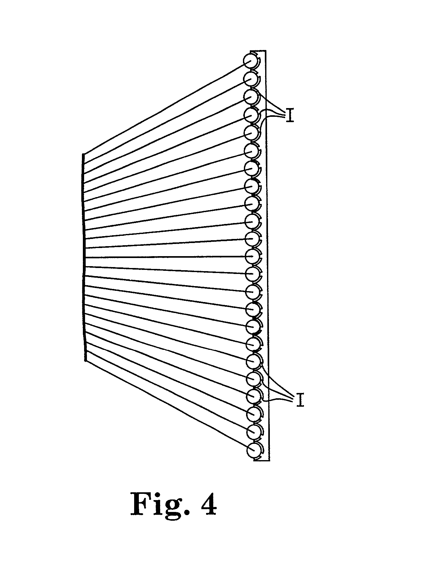
[0008]The present invention provides a microlens sheeting having a composite image that appears to be suspended above or below the sheeting. These suspended images are referred to for convenience as floating images, and they can be located above or below the sheeting (either as two or three-dimensional images), or can be a three-dimensional image that appears above, in the plane of, and below the sheeting. The images can be in black and white or in color, and can appear to move with the observer. Unlike some holographic sheetings, imaged sheeting of the present invention cannot be used to create a replica of itself. Additionally, the floating image(s) can be observed by a viewer with the unaided eye.
[0009]The inventive sheeting having a composite image as described may be used in a variety of applications such as securing tamperproof images in passports, ID badges, banknotes, event passes, affinity cards, product identification formats and advertising promotions for verification and authenticity, brand enhancement images which provide a floating or sinking or a floating and sinking image of the brand, identification presentation images in graphics applications such as emblems for police, fire or other emergency vehicles; information presentation images in graphics applications such as kiosks, night signs, vehicles and automotive dashboard displays; decoration for apparel and fashion accessories; retroreflective safety clothing and equipment; and novelty enhancement through the use of composite images on products such as business cards, hang-tags, art, shoes and bottled products.
[0010]The present invention further provides a novel means of forming imaged sheeting containing the described composite images. In one embodiment a single composite image is formed. Embodiments are also disclosed in which two or more composite images are formed, as well as composite images that appear to be both above and below the sheeting. Other embodiments could consist of combinations of conventionally printed images and composite images formed by this invention.

Problems solved by technology

That is, the perceived depth of the image is inverted so that the object appears “inside out.” This is a major disadvantage, because to correct the image it is necessary to achieve two optical inversions.
These methods are complex, involving multiple exposures with a single camera, or multiple cameras, or multi-lens cameras, to record a plurality of views of the same object, and require extremely accurate registration of multiple images to provide a single three-dimensional image.
Further, any method that relies on a conventional camera requires the presence of a real object before the camera.
This further renders that method ill-adapted for producing three-dimensional images of a virtual object (meaning an object that exists in effect, but not in fact).
A further disadvantage of integral photography is that the composite image must be illuminated from the viewing side to form a real image that may be viewed.

Method used


Image

  • Sheeting with composite image that floats
  • Sheeting with composite image that floats
  • Sheeting with composite image that floats

Examples


examples

[0074]This invention will be further explained by the following Examples, which may for convenience reference certain of the Figures.

example one

[0075]This example describes an embedded lens sheeting with an aluminum material layer, and a composite image that appeared to float above the sheeting. An optical train of the type depicted in FIG. 14 was used to form the floating image. The optical train consisted of a Spectra Physics Quanta-Ray™ DCR-2(10)Nd:YAG laser 300 operating in a Q-switched mode at its fundamental wavelength of 1.06 micrometers. The pulse width of this laser is typically from 10–30 ns. Following the laser, the energy was redirected by a 99% reflective turning mirror 302, a ground glass diffuser 304, a 5× beam expansion telescope 306, and an aspheric lens 308 with a numerical aperture of 0.64 and a focal length of 39.0 mm. The light from the aspheric lens 308 was directed toward an XYZ stage 310. The stage was composed of three linear stages, and is available from Aerotech Inc. of Pittsburgh, Pa. under the designation ATS50060. One linear stage was used to move the aspheric lens along the axis between the as...

example two

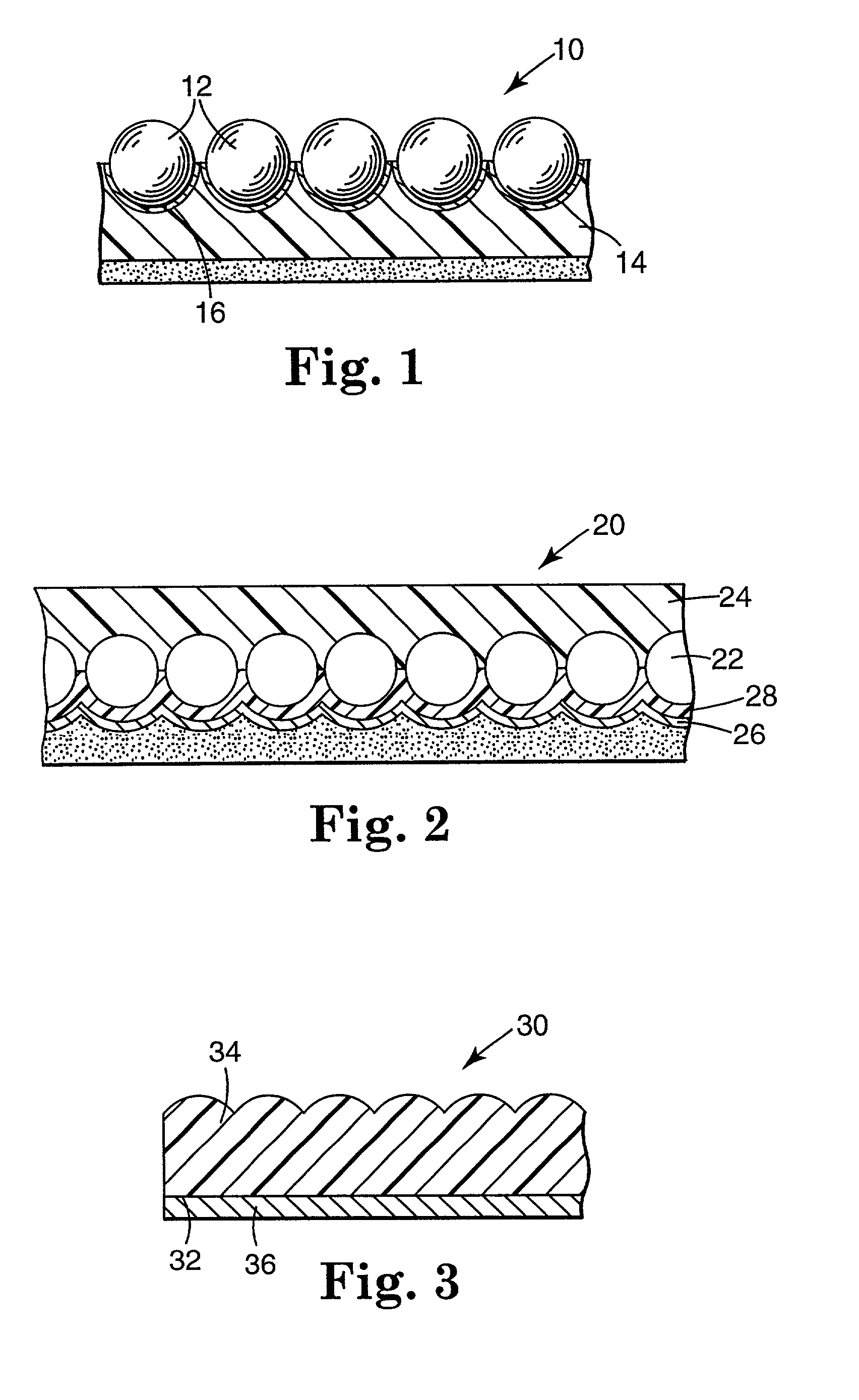
[0080]In this example, an exposed lens sheeting construction with a transparent mirror radiation sensitive layer was used to form a composite image that appeared to float below the microlens sheeting. The optical train used in Example One was also used in this Example. The microlensed sheeting was positioned relative to the aspheric lens 308 so that the lens was nearly in contact with the microlens sheeting. The laser output was adjusted to achieve approximately 14 mJ / cm2 directly beneath the aspheric lens. The exposed lens sheeting consisted of partially embedded microspheres as described in U.S. Pat. No. 3,801,183, with a zinc-sulfide (ZnS) dielectric mirror vapor deposited onto one side of the microspheres. The thickness of the ZnS layer was nominally 60 nm. As in Example One, the laser was operated at 10 Hz while the sheeting was moved at 50.8 cm / min, resulting in the formation of continuous composite lines in the microlensed sheeting. A “globe” pattern (a circle with four inscr...


PUM

PropertyMeasurementUnit
refractive indexaaaaaaaaaa
diametersaaaaaaaaaa

Abstract

Microlens sheetings with composite images are disclosed, in which the composite image floats above or below the sheeting, or both. The composite image may be two-dimensional or three-dimensional. Methods for providing such an imaged sheeting, including by the application of radiation to a radiation sensitive material layer adjacent the microlenses, are also disclosed.

Description

[0001]This is a continuation-in-part of U.S. application Ser. No. 09 / 510,428, filed Feb. 22, 2000 now U.S. Pat. No. 6,288,842.FIELD OF THE INVENTION[0002]The present invention relates to sheeting that provides one or more composite images that are perceived by an observer to be suspended in space relative to the sheeting, and in which the perspective of the composite image changes with the viewing angle.BACKGROUND OF THE INVENTION[0003]Sheeting materials having a graphic image or other mark have been widely used, particularly as labels for authenticating an article or document. For example, sheetings such as those described in U.S. Pat. Nos. 3,154,872; 3,801,183; 4,082,426; and 4,099,838 have been used as validation stickers for vehicle license plates, and as security films for driver's licenses, government documents, tape cassettes, playing cards, beverage containers, and the like. Other uses include graphics applications for identification purposes such as on police, fire or other...

Claims


Application Information

Patent Timeline
Patent Type & Authority Patents(United States)
IPC IPC(8): G02B27/10B42D15/00G03B35/00B41M3/00B41M3/14G02B1/00G02B3/00G02B5/128G02B25/00G02B27/00G02B30/27G03C9/08G09F19/12
CPCG02B27/2292G02B27/106G02B27/1066G02B27/123G02B27/2214G02B5/128A41D27/08A41D31/0088B41M3/003B41M3/148A41D31/32G02B30/56G02B30/27
Inventor FLORCZAK, JEFFREY M.KRASA, ROBERT T.MAKI, STEPHEN P.OSGOOD, III, RICHARD M.
Owner 3M INNOVATIVE PROPERTIES CO
Why Eureka
Try Eureka