Signal processor

a signal processor and signal technology, applied in the field of signal processors, can solve the problems of difficult real-time processing of data and inapplicable methods, and achieve the effect of improving signal processing capability and simple circuit structur

Inactive Publication Date: 2006-06-27
PANASONIC CORP
View PDF9 Cites 5 Cited by
  • Summary
  • Abstract
  • Description
  • Claims
  • Application Information

AI Technical Summary

Benefits of technology

[0015]According to the present invention, the influences of a vertically asymmetric waveform (resulting from an asymmetry phenomenon which occurs during manufacturing of the disk, or the like) and a tilted disk (resulting from warping of the disk, or the like) on the system can be corrected with a relatively simple circuit structure. Moreover, the quality of a transmission path can be quantitatively determined on the time base. This enables implementation of real-time feedback to the system. By compensating for the quality of the transmission path by combination of the present invention and one or more of the existing various signal processing methods, a signal processor capable of not only improving the signal processing capability but also compensating for the quality can be obtained.

Problems solved by technology

However, this method is not practical because it is difficult to process data in real time and a large circuit scale is required in order to deal with a large amount of data.

Method used


Image

  • Signal processor
  • Signal processor
  • Signal processor

Examples


Embodiment Construction

[0023]Hereinafter, an embodiment of the present invention will be described in detail with reference to the accompanying drawings. Note that the same or corresponding portions are denoted with the same reference numerals and characters, and description thereof will not be repeated. [Overall Structure of the Optical-Disk Play-Back Apparatus]

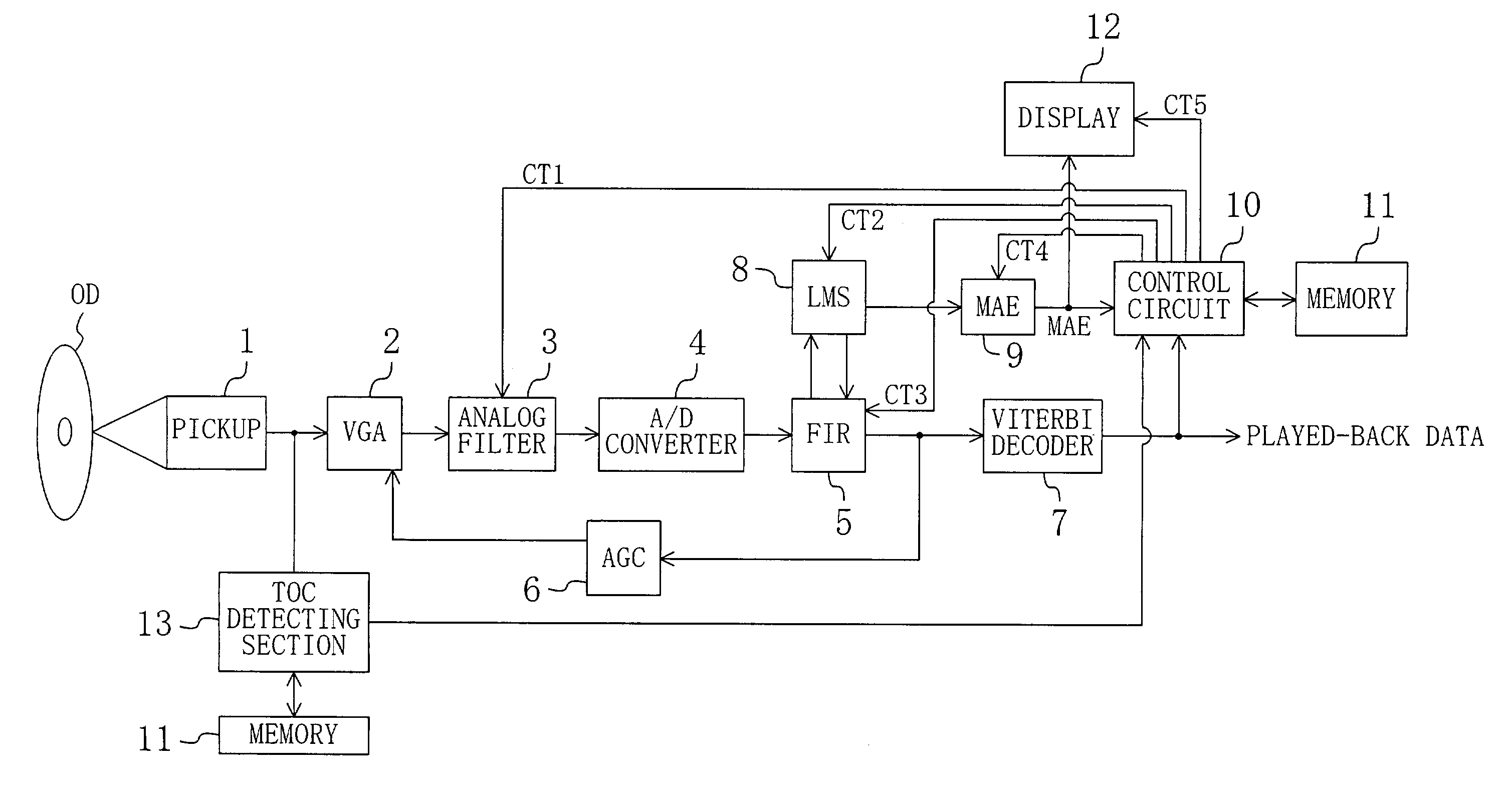
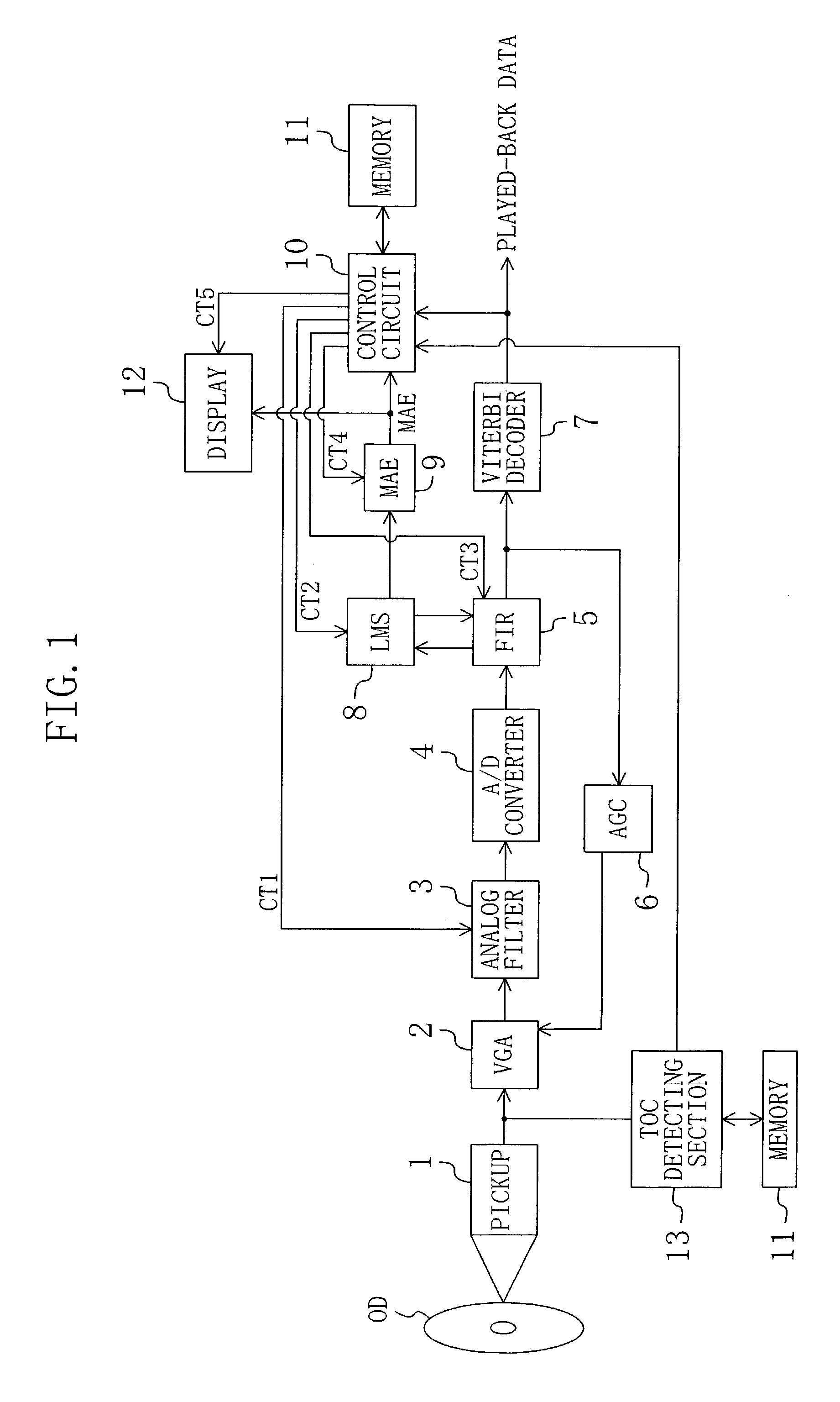
[0024]FIG. 1 is a block diagram showing the overall structure of an optical-disk play-back apparatus according to an embodiment of the present invention. The play-back apparatus of FIG. 1 processes a played-back signal from an optical disk by PRML (Partial Response Maximum Likelihood) signal processing technology. The play-back apparatus of FIG. 1 includes a pickup 1, a variable gain amplifier (VGA) 2, an analog filter 3, an analog-to-digital (A-D) converter 4, a transversal filter (FIR (Finite Impulse Response) filter) 5, an automatic gain control circuit (AGC) 6, a Viterbi decoder 7, an LMS (Least Mean Square) circuit 8, an MAE (Mean Absolute Er...


PUM

PropertyMeasurementUnit
ODaaaaaaaaaa
frequencyaaaaaaaaaa
structureaaaaaaaaaa

Abstract

The signal processor includes an analog filter, an analog-to-digital (A-D) converter, an adaptive equalization filter, a quality value calculating circuit, and a control circuit. The analog filter removes high-frequency noises of a played-back signal from a recording medium and amplifies a specific frequency band of the played-back signal. The A-D converter converts the played-back signal from the analog filter into a digital signal. The adaptive equalization filter performs waveform equalization of the played-back signal from the A-D converter while adjusting a tap coefficient of the adaptive equalization filter so as to reduce a difference between an output of the adaptive equalization filter and a target value. The quality value calculating circuit calculates a quality value based on the difference between the output of the adaptive equalization filter and the target value. The control circuit compares the quality value calculated by the quality value calculating circuit with a predetermined reference value, and conducts a process for improving the quality value according to the comparison result.

Description

BACKGROUND OF THE INVENTION[0001]The present invention generally relates to a signal processor. More particularly, the present invention relates to a signal processor for processing a played-back signal from a recording medium such as a magnetic disk and an optical disk.[0002]There is a variation between manufactured play-back apparatuses for a magnetic disk and an optical disk in terms of the capability (quality) of accurately playing back data recorded on the disk. Accordingly, the play-back apparatuses for a magnetic disk and an optical disk have a function to evaluate the quality of the apparatus. If the quality of the apparatus is low, various adjustments are made in order to improve the quality. For example, the quality of the apparatus is evaluated and adjustments of the apparatus are made if the apparatus gets out of order during inspection before shipment, or after shipment.[0003]One example of a method for evaluating the quality of the play-back apparatus is to measure the...

Claims


Application Information

Patent Timeline
Patent Type & Authority Patents(United States)
IPC IPC(8): G11B7/00H04N5/85G11B20/10H04B3/06H04N5/93
CPCG11B20/10009G11B20/10296G11B20/10046G11B20/10
Inventor MOURI, HIROKINAKAHIRA, HIROYUKIYAMAMOTO, AKIRA
Owner PANASONIC CORP
Why Eureka
Try Eureka