Multi-stage code generator and decoder for communication systems

a communication system and code generator technology, applied in the field of encoding and decoding data in communications systems, can solve the problems of inefficiency, often occurring packet loss, and inability to meet the needs of one-to-many or many-to-many communications, and achieve the effects of reducing the number of codes, reducing the number of code generators, and improving the quality of cod

Inactive Publication Date: 2006-06-27
QUALCOMM INC
View PDF8 Cites 212 Cited by
  • Summary
  • Abstract
  • Description
  • Claims
  • Application Information

AI Technical Summary

Benefits of technology

[0017]According to one embodiment of the invention, a method of encoding data for transmission from a source to a destination over a communications channel is provided. The method operates on an ordered set of input symbols and includes generating a plurality of redundant symbols from the input symbols. The method also includes generating a plurality of output symbols from a combined set of symbols including the input symbols and the redundant ...

Problems solved by technology

Lost data (erasures) are often easier to deal with than corrupted data (errors) because the recipient cannot always tell when corrupted data is data received in error.
On the Internet, packet loss often occurs because sporadic congestion causes the buffering mechanism in a router to reach its capacity, forcing it to drop incoming packets.
However, TCP is often not suitable for one-to-many or many-to-many communications or where the sender and the recipient independently determine when and where they will transmit or receive data.
Although acknowledgment-based protocols are generally suitable for many applications and are in fact widely used over the current Internet, they are inefficient, and sometimes completely infeasible, for certain applications as such as those described in U.S. Pat. No. 6,307,487 issued to Michael G. Luby entitled “Information Additive Code Generator and Decoder for Communication Systems” (hereinafter “Luby I”).
Furthermore, acknowledgment-based protocols do not scale well to broadcasting, where one sender is sending a file simultaneously to multiple users.
Protocols that rely on acknowledgment data (either positive or negative) for reliable delivery of the file require a back channel from each recipient to the sender, and this can be prohibitively expensive to provide.
Furthermore, this requires a complex and powerful sender to be able to properly handle all of the acknowledgment data sent from the recipients.
Another drawback is that if different recipients lose different sets o...

Method used


Image

  • Multi-stage code generator and decoder for communication systems
  • Multi-stage code generator and decoder for communication systems
  • Multi-stage code generator and decoder for communication systems

Examples


Embodiment Construction

[0046]The present disclosure references U.S. Pat. No. 6,307,487 (Luby I), and U.S. Pat. No. 6,320,520 issued to Michael G. Luby entitled “Information Additive Group Code Generator and Decoder for Communication Systems” (hereinafter “Luby II”), the entire disclosures of which are herein incorporated by reference for all purposes. Luby I and Luby II provide teachings of systems and methods that can be employed in certain embodiments according to the present invention. It is to be understood, however, that these systems and methods are not required of the present invention, and many other variations, modifications, or alternatives can also be used.

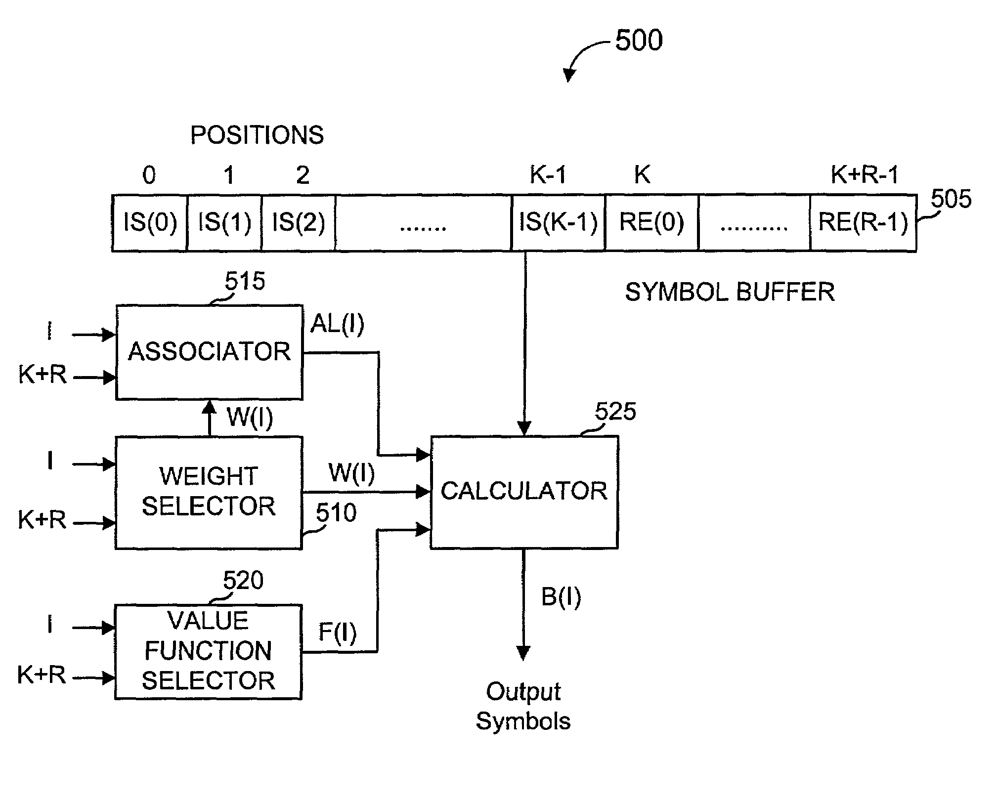
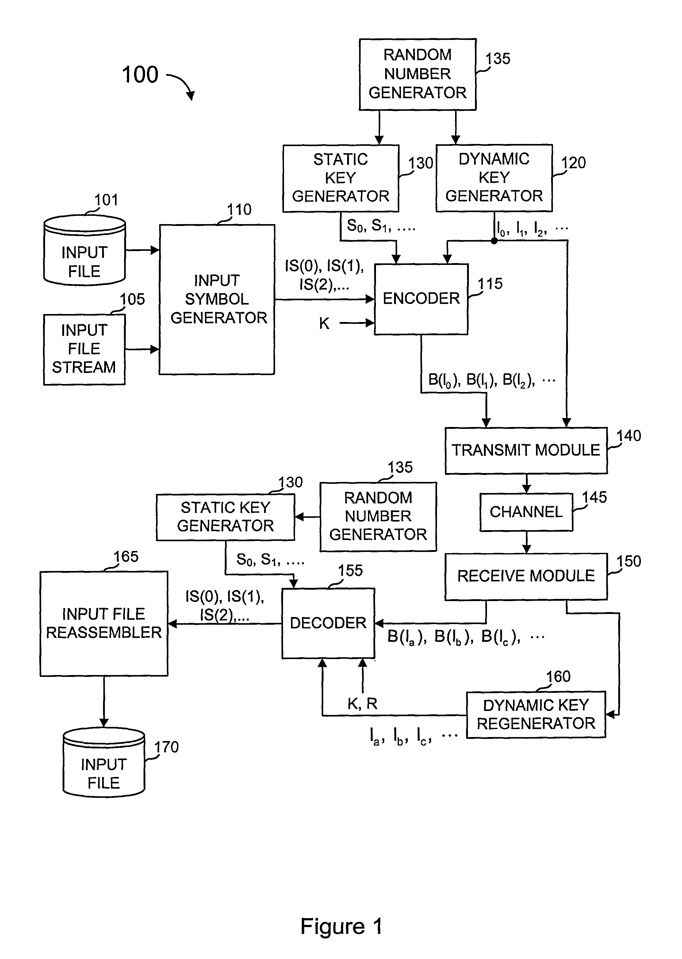
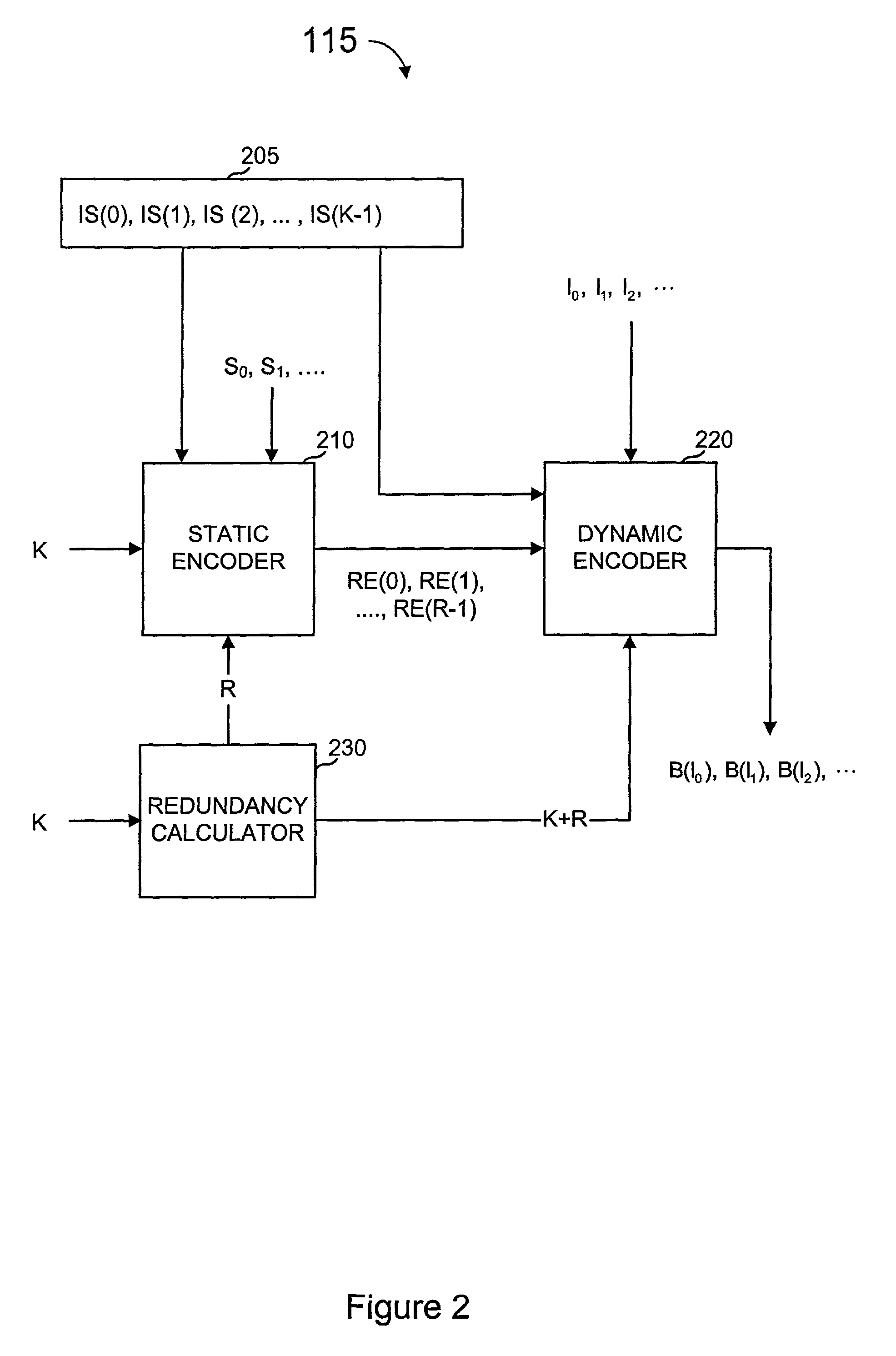
[0047]In the specific embodiments described herein, a coding scheme denoted as “multi-stage coding” is described, preceded by an explanation of the meaning and scope of various terms used in this description.

[0048]Multi-stage encoding, as described herein, encodes the data in a plurality of stages. Typically, but not always, a first stage add...


PUM


Abstract

A method of encoding data for transmission from a source to a destination over a communications channel is provided. A plurality of redundant symbols are generated from an ordered set of input symbols to be transmitted. A plurality of output symbols are generated from a combined set of symbols including the input symbols and the redundant symbols, wherein the number of possible output symbols is much larger than the number of symbols in the combined set of symbols, wherein at least one output symbol is generated from more than one symbol in the combined set of symbols and from less than all of the symbols in the combined set of symbols, and such that the ordered set of input symbols can be regenerated to a desired degree of accuracy from any predetermined number, N, of the output symbols.

Description

BACKGROUND OF THE INVENTION[0001]The present invention relates to encoding and decoding data in communications systems and more specifically to communication systems that encode and decode data to account for errors and gaps in communicated data.[0002]Transmission of files between a sender and a recipient over a communications channel has been the subject of much literature. Preferably, a recipient desires to receive an exact copy of data transmitted over a channel by a sender with some level of certainty. Where the channel does not have perfect fidelity (which covers most all physically realizable systems), one concern is how to deal with data lost or garbled in transmission. Lost data (erasures) are often easier to deal with than corrupted data (errors) because the recipient cannot always tell when corrupted data is data received in error. Many error-correcting codes have been developed to correct for erasures and / or for errors. Typically, the particular code used is chosen based ...

Claims


Application Information

Patent Timeline
IPC IPC(8): H04K1/02H03M13/00H03M13/19H03M7/00H03M13/11H03M13/29H03M13/37H03M13/47H04L1/00H04L25/49H04L27/04
CPCH04L1/0041H03M13/3761H03M13/1102H03M13/19H04L2001/0093H03M7/00H03M13/00H04L27/04
Inventor SHOKROLLAHI, M. AMINLASSEN, SORENLUBY, MICHAEL
Owner QUALCOMM INC
Why Eureka
Try Eureka