Synchronous detection method and device, and sensor signal detector

Active Publication Date: 2006-06-27
DENSO CORP
View PDF5 Cites 26 Cited by
  • Summary
  • Abstract
  • Description
  • Claims
  • Application Information

AI Technical Summary

Benefits of technology

[0009]The present invention attempts to overcome the foregoing problems. An object of the present invention is to provide a synchronous detection method and device capable of efficiently minimizing high-frequenc

Problems solved by technology

The synchronous detection circuit has a drawback that switching of connections through a switch and selection of a signal path are synchronized with the reference signal and this causes high-frequency noise.
The high-frequency noise degrades the si

Method used


Image

  • Synchronous detection method and device, and sensor signal detector
  • Synchronous detection method and device, and sensor signal detector
  • Synchronous detection method and device, and sensor signal detector

Examples


first embodiment

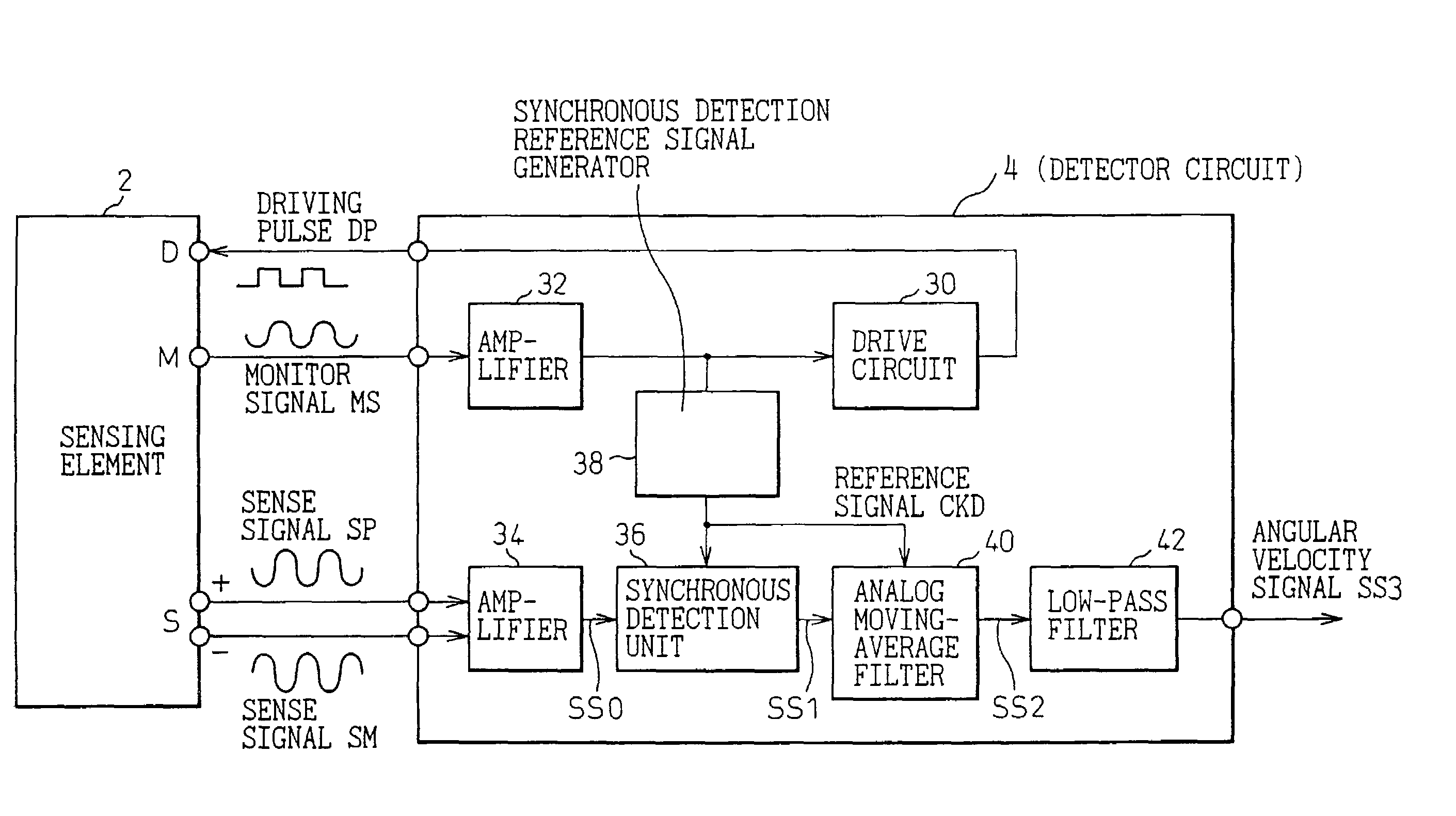
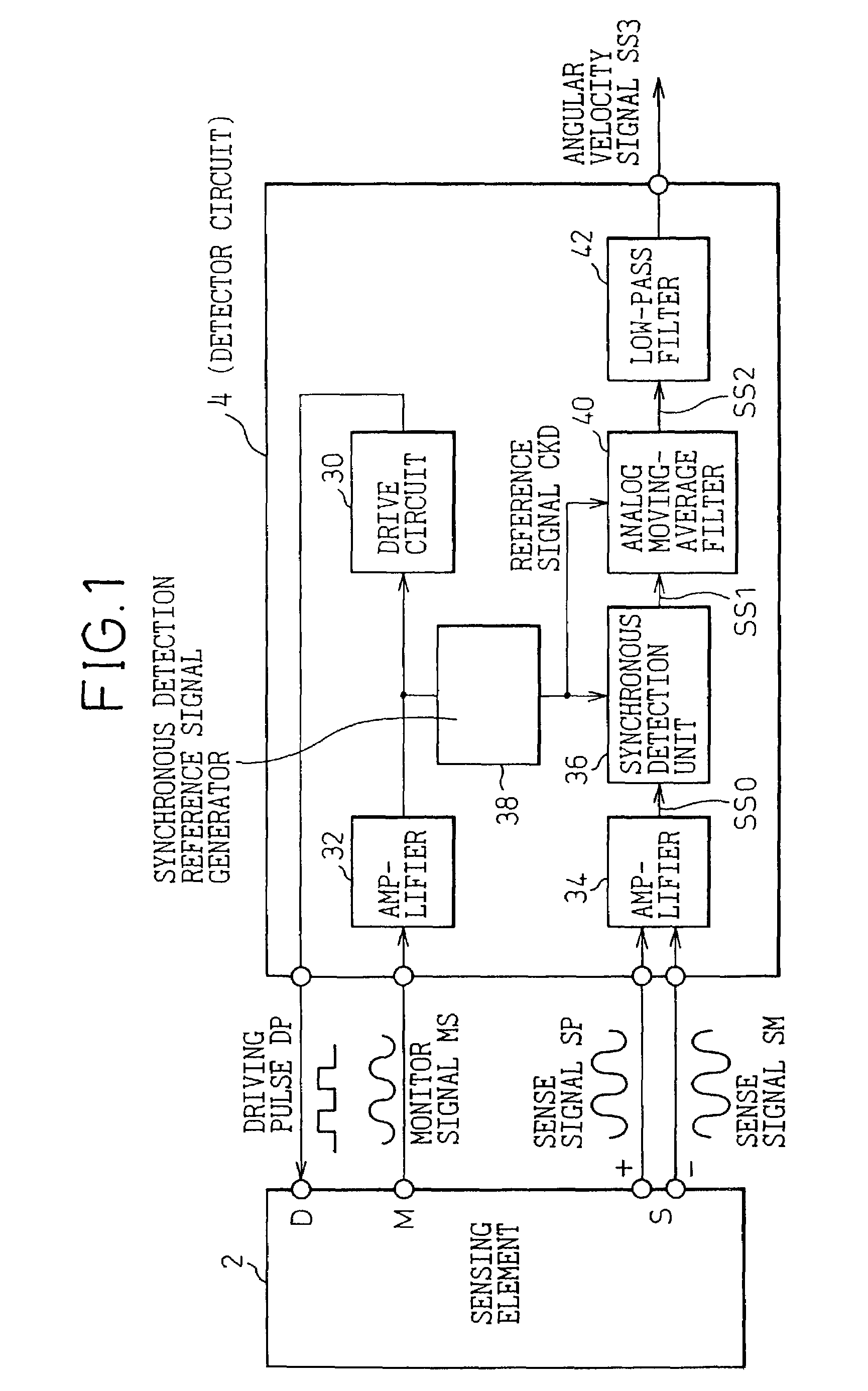
[0066]FIG. 1 is a block diagram showing the overall configuration of an angular velocity detector to which the first embodiment of the present invention is adapted.

[0067]The angular velocity detector of the present embodiment is a so-called vibratory gyroscope. The angular velocity detector consists of a sensing element 2 that is a vibrator, and a detector circuit 4 (corresponding to a sensor signal detector in accordance with the present invention) that drives the sensing element 2 and detects an angular velocity at which the angular displacement of the vibrator has changed due to an external factor.

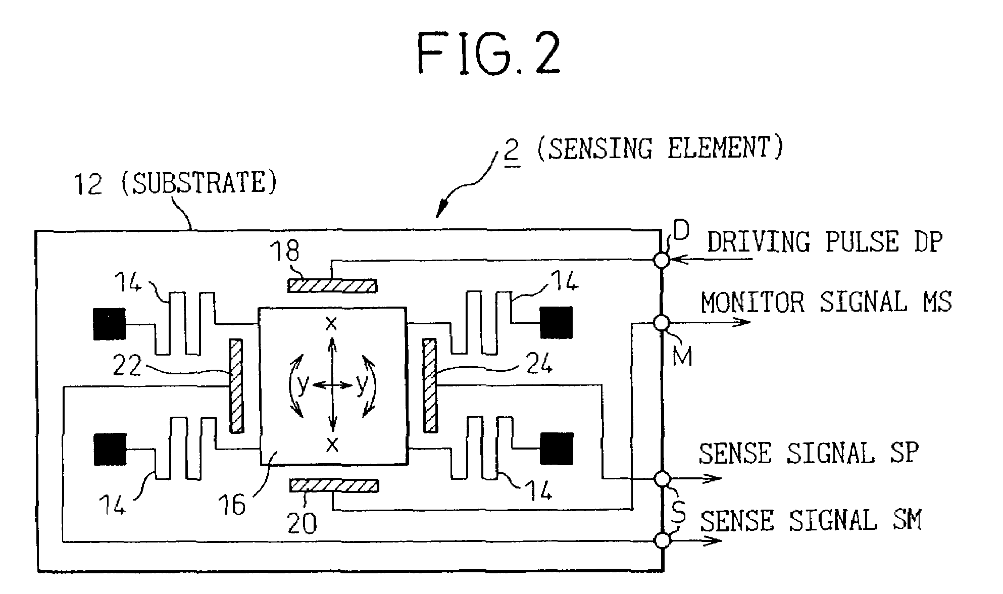
[0068]The sensing element 2 has, for example, as shown in FIG. 2, a substantially rectangular vibrator 16 mounted on a substrate 12 made of a monocrystalline silicon or the like by way of four beams 14 extending from the corners of the substrate. A driving electrode 18, a monitor electrode 20, and a pair of detection electrodes 22 and 24 are disposed around the vibrator 16. The driving ...

second embodiment

[0092]FIG. 7 is a block diagram showing the overall configuration of an angular velocity detector to which the second embodiment is adapted.

[0093]The angular velocity detector to which the present embodiment is adapted has basically the same configuration as the angular velocity detector to which the first embodiment is adapted. Differences from the first embodiment will be described below. Namely, the vibrator 16 included in the sensing element 2 is vibrated with a driving signal that is produced by superposing a carrier CR on a driving pulse DP produced by the drive circuit 30. The frequency of the carrier CR is higher than the frequency of the driving pulse DP (for example, 1 MHz). Thus, the carrier CR is superposed on the sense signals SP and SM that are produced by the sensing element 2 (eventually, on the sense signal SS0 produced by the differential amplifier 34). The sense signal SS0 produced by the differential amplifier 34 is detected using the reference signal CKD synchro...

third embodiment

[0107]FIG. 10 is a block diagram showing the overall configuration of an angular velocity detector to which the third embodiment is adapted.

[0108]The angular velocity detector to which the present embodiment is adapted is basically identical to the one to which the first embodiment is adapted. Differences from the first embodiment will be described below. Namely, a time-domain analog-to-digital (A / D) converter with the capability of a filter 60 is included for realizing the capability of an analog moving-average filter. The temporal A / D converter with the capability of a filter 60 is used to produce an analog moving average of the detection signal SS1. The result of the production is A / D converted. Moreover, a digital moving average of digital data Da produced by the temporal A / D converter 60 is produced using a digital moving-average filter 80. Consequently, digital data DT is transmitted as the angular velocity signal SS3.

[0109]The foregoing differences will be described below.

[01...


PUM


Abstract

The present invention is intended to efficiently minimize high-frequency noise stemming from synchronous detection without the necessity of a low-pass filter that requires a large time constant. A vibratory gyroscope includes a synchronous detection unit that detects a sense signal sent from a sensing element using a reference signal synchronous with a monitor signal. In the vibratory gyroscope, an analog moving-average filter that produces a moving average of the detection signal by sampling the detection signal during one cycle of the reference signal is used to remove high-frequency noise components from the detection signal, which is detected to be synchronous with the reference signal, without the necessity of a CR filter that requires a large time constant. Consequently, unnecessary noise components whose frequencies are equal to the frequency of the reference signal and those of its harmonics, and which stem from synchronous detection, can be efficiently attenuated owing to an infinite attenuation frequency band offered by the analog moving-average filter.

Description

BACKGROUND OF THE INVENTION[0001]1. Field of the Invention[0002]The present invention relates to a synchronous detection method, and a device, that are used to sample a signal component synchronous with a reference signal from an input signal, and to a sensor signal detector utilizing the synchronous detection.[0003]2. Description of the Related Art[0004]In the past, a synchronous detection circuit has been used to separate a desired signal component from an input signal that suffers a poor signal-to-noise ratio or to detect a phase difference of an input signal from a reference signal.[0005]The synchronous detection circuit performs full-wave rectification on a signal, of which the frequency falls within a predetermined frequency band, using a reference signal of the frequency, and thus restores a desired signal. The synchronous detection circuit has a drawback that switching of connections through a switch and selection of a signal path are synchronized with the reference signal a...

Claims


Application Information

Patent Timeline
IPC IPC(8): H03D1/04G01C19/56G01C19/5726G01C19/5755G01P15/09H03D9/00H03H17/02
CPCG01C19/5649G01P15/18G01P15/09
Inventor WATANABE, TAKAMOTO
Owner DENSO CORP
Why Eureka
Try Eureka