Passive athermal fiber bragg grating strain gage

a technology of athermal fiber bragg grating and strain gage, which is applied in the field of optical fiber sensors, can solve the problems of limiting the total number of sensors in a given sensing network, restricting the adjustment of fbg sensitivity to the set of discrete values, and too complex and difficult to implement in real world structures, so as to improve the positive temperature sensitivity and reduce the negative temperature sensitivity

Active Publication Date: 2006-06-27
ARAUJO FRANCISCO MANUEL MOITA +1
View PDF1 Cites 25 Cited by
  • Summary
  • Abstract
  • Description
  • Claims
  • Application Information

AI Technical Summary

Benefits of technology

[0015]This method enables not only annulled temperature sensitivity, i.e., TS=0, but also enhanced positive temperature sensitivity, i.e., TS>βT, reduced positive temperature sensitivity, i.e., TS<βT, or even negative temperature sensitivity, i.e., TS<0. In the particular case of annulled temperature sensitivity, the exact balancing between the intrinsic FBG temperature sensitivity and temperature induced strain, βT=−βεε( ) / ΔT, provides so-called athermal operation of the strain gage.

Problems solved by technology

2226–2234 (2000)] have been demonstrated, but they are often too complex and difficult to implement in real world structures.
Moreover, besides being not required in all the strain monitoring cases, the measurement of temperature by the referred methods implies the allocation of additional bandwidth to each sensor, therefore limiting the total number of sensors in a given sensing network.
However, this restricts the adjustment of the FBG sensitivity to the set of discrete values that can be obtained employing available materials.

Method used


Image

  • Passive athermal fiber bragg grating strain gage
  • Passive athermal fiber bragg grating strain gage
  • Passive athermal fiber bragg grating strain gage

Examples


Embodiment Construction

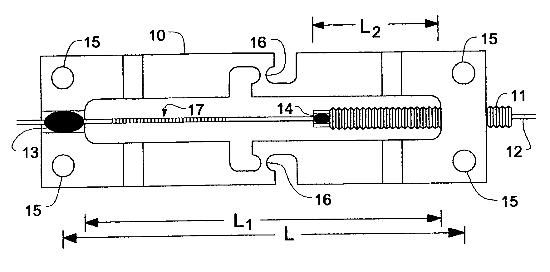
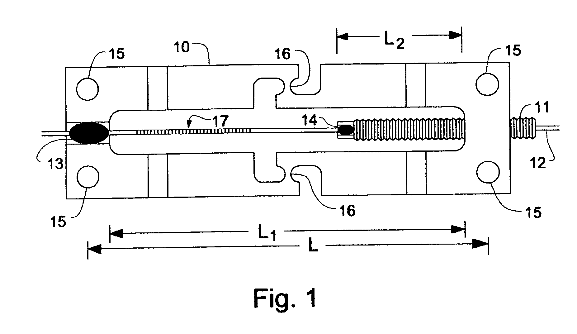
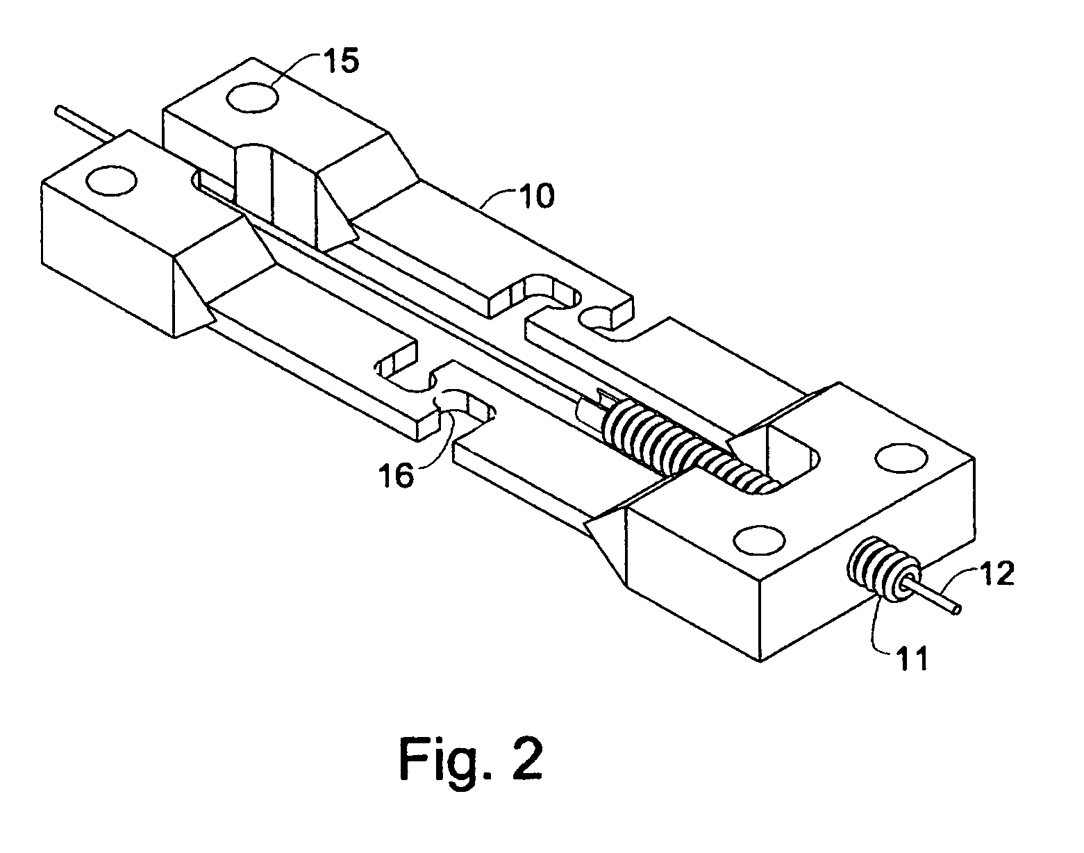
[0018]FIGS. 1 and 2 are plan and isometric views of a preferred embodiment of an athermal FBG strain gage according to the present invention. Other embodiments and variations are within the scope of the invention as claimed.

[0019]An athermal FBG strain gage according to the present invention has a frame 10, a pointer 11, an optical fiber 12, fiber-to-frame engagement means 13, and fiber-to-pointer engagement means 14. The fiber-to-frame engagement means 13 and fiber-to-pointer engagement means 14 are adhesives, such as epoxies; alternatively, other means known in the art for fixing optical fibers to supporting structures may be used. Means for fixing the frame to a structural element to be monitored are also provided. In the preferred embodiment, fixing holes 15 which accommodate fasteners such as rivets, bolts, or screws are the means used to attach the strain gage frame to the structure being monitored. Alternatively, other fastening means such as welding may be employed. The fram...


PUM


Abstract

Fiber Bragg gratings (FBGs) are particular suitable for measuring strain. However, a single parameter measurement is difficult to implement, since cross-sensitivity to temperature compels the use of an additional temperature reference, e.g. a strain-inactive FBG. The development of a passive athermal fiber Bragg grating strain gage is thus of particular interest since it renders optional the measurement of temperature, benefiting large scale system design and performance. In view of this need, a package for fiber Bragg gratings that enables strain measurements to be performed while canceling temperature sensitivity is disclosed. The proposed design is based on a structure composed of two parts, which can be made of the same material, having a defined length ratio that allows the adjustment of the temperature sensitivity to zero, providing athermal operation of the strain gage. Moreover, the disclosed passive athermal scheme is adjustable to further compensate for structural thermal expansion, enabling the load-induced strain component to be decoupled from the temperature-induced strain component.

Description

FIELD OF THE INVENTION[0001]The present invention relates to optical fiber sensors and, more particularly, pertains to fiber Bragg grating strain gages with adjustable compensation for thermal effects.BACKGROUND[0002]A fiber Bragg grating (FBG) is a periodic modulation of the refractive index of the core of a single mode optical fiber usually written by exposure to UV light. This periodic structure is characterized by a narrow reflective spectral response. The center wavelength λB of the reflection band matches the Bragg condition:λB=2neffΛ,  (1)where neff is the effective index of the guided mode and Λ is the period of the index modulation. The FBG resonance wavelength will vary accordingly with temperature and / or strain changes experienced by the fiber. For a temperature change ΔT; the corresponding wavelength shift is given by:[0003]ΔλB=λB⁡(1Λ⁢∂Λ∂T+1n⁢∂n∂T)⁢Δ⁢⁢T=λB⁡(αF+ξ)⁢Δ⁢⁢T=λB⁢βT⁢Δ⁢⁢T,(2)where αF is the fiber coefficient of thermal expansion (CTE) and ξ is the fiber thermo-opt...

Claims


Application Information

Patent Timeline
Patent Type & Authority Patents(United States)
IPC IPC(8): G02B6/00
CPCG01L1/246
Inventor ARAUJO, FRANCISCO MANUEL MOITAFERREIRA, LUIS ALBERTO DE ALMEIDA
Owner ARAUJO FRANCISCO MANUEL MOITA
Why Eureka
Try Eureka