Estimating maximum friction coefficient based on knowledge of the loads and self-alignment torque generated in a tire contact zone

a technology of load and friction coefficient, applied in vehicle tyre testing, brake systems, instruments, etc., can solve the problems of tire deformation modification, high sensitive to road surface condition, etc., and achieve the effect of increasing the dynamic range of signal variation

Inactive Publication Date: 2006-06-27
MICHELIN & CO CIE GEN DES ESTAB MICHELIN
View PDF5 Cites 27 Cited by
  • Summary
  • Abstract
  • Description
  • Claims
  • Application Information

AI Technical Summary

Benefits of technology

[0003]The present invention also relates to the various electronic assistance devices used, for example, for antilock control of the brakes of a vehicle or antiskid control of the drive wheels, control of the trajectory of a vehicle or alternatively for other forms of control or monitoring, for instance the tire pressures. It is known that such devices reconstruct the grip coefficient (μ) of the tires on the road by calculation, without having carried out any measurement either of the grip coefficient or of the forces developed in the contact of the tires with the ground. Even though these devices provide significant assistance and extra safety, their operation would benefit greatly from the use of a measured value, or a value estimated on the basis of real measurements carried out on the tire during operation.
[0005]The various electronic assistance devices mentioned above would therefore usefully benefit from “real-time” indications of the forces and the grip conditions liable to affect the handling of a vehicle, especially when it undergoes an acceleration due to a driving force or a braking force, or due to a change of direction of movement. The invention aims to provide a method of achieving this efficiently.
[0026]It should be noted that, in the event that the circumferential extension of the sidewalls is being measured within the sidewalls at a position different from their flexurally neutral fiber, the circumferential extension will include a component due to the flexure of the sidewall, in particular when passing through the contact area (a phenomenon also referred to as “bellying”). This component due to flexure is by no means a problem, and it can be exploited in order to increase the dynamic range of variation of the signals which the invention uses, by carrying out the extension measurement elsewhere than on the flexurally neutral fiber.

Problems solved by technology

Furthermore, the estimates provided by these sensors are local and therefore highly sensitive to the surface condition of the road.
This leads to a modification of the deformations of the tire.

Method used


Image

  • Estimating maximum friction coefficient based on knowledge of the loads and self-alignment torque generated in a tire contact zone
  • Estimating maximum friction coefficient based on knowledge of the loads and self-alignment torque generated in a tire contact zone
  • Estimating maximum friction coefficient based on knowledge of the loads and self-alignment torque generated in a tire contact zone

Examples


Embodiment Construction

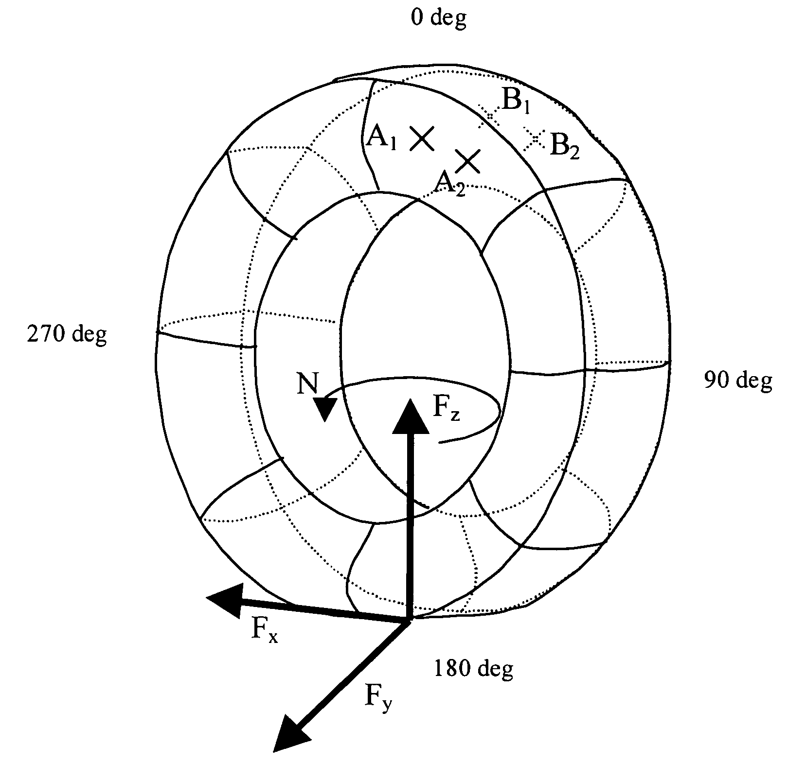
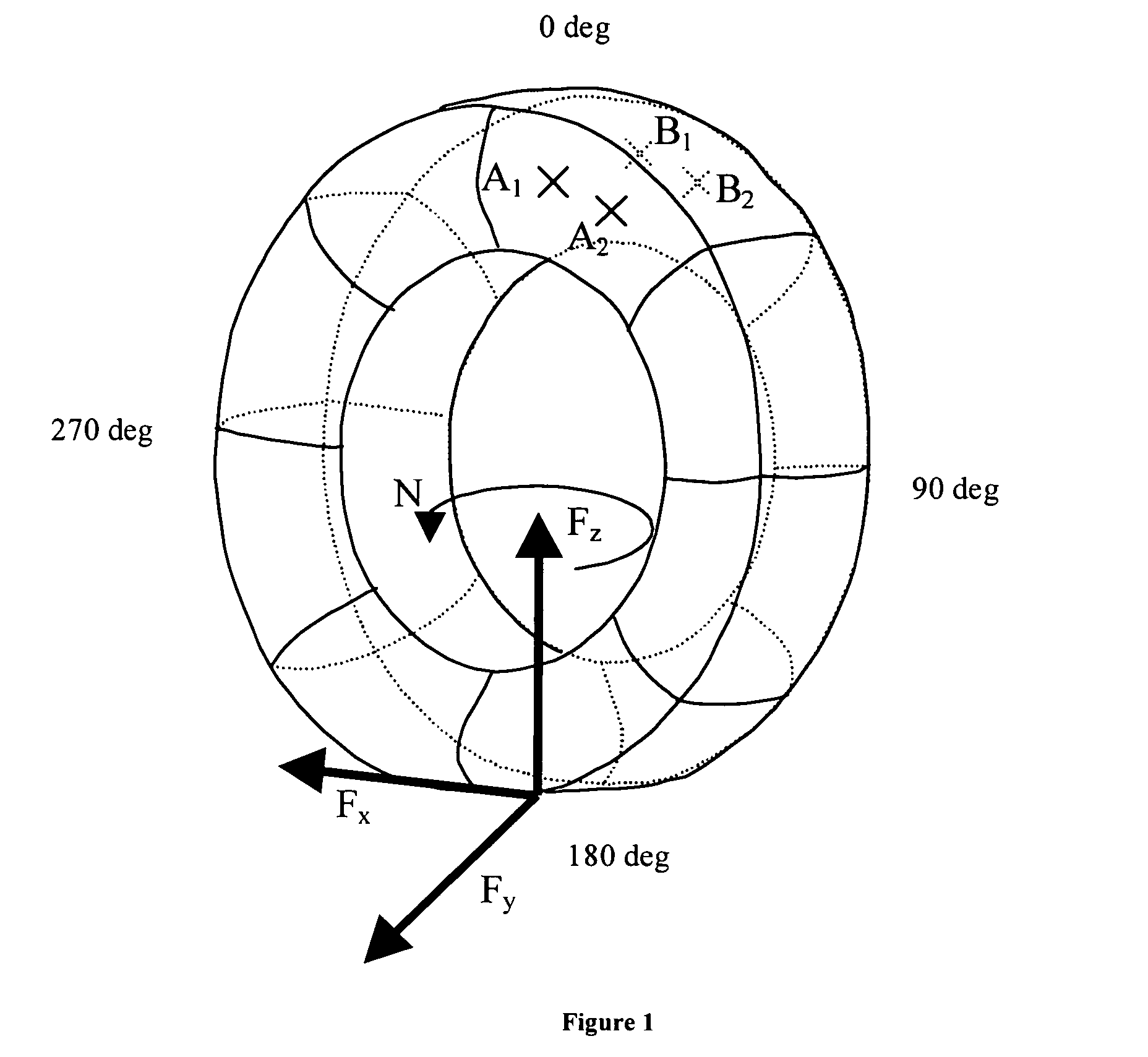
[0066]The method described here relies on the fact that each force applied to the tire in the contact area causes a modification of the circumferential extension of the sidewalls of the tire. The case of an inflated tire fitted on its wheel will be considered, on whose first sidewall two points A1 and A2 are identified (FIG. 1), which are placed at the same radius but are separated in the circumferential direction. On the second sidewall, at the same azimuths as A1 and A2 and at the same radius, two points B1 and B2 are selected. In the absence of any forces being applied to the tire, the distance which separates the two points is constant as a function of the angle of rotation of the tire-wheel assembly. The azimuth θ will be defined as the angle at which the circumferential extension of the sidewalls is being analyzed. The origin of the azimuth is taken on the side opposite to the center of the contact area. The center of the contact area therefore has the azimuth 180°.

[0067]When ...


PUM


Abstract

A method for estimation of the maximum grip coefficient on the basis of knowledge of the forces and the self-alignment torque which are generated in the contact area of a tire, includes the steps of:selecting a plurality of fixed points in space, which lie at different azimuths along the circumference in at least one sidewall of the tire,carrying out a corresponding number of measurements of circumferential distance variation (extension or contraction) at these fixed points when the tire is rolling on the road,processing the measurement signals so as to extract the three components of a resultant of forces which are exerted by the road on the contact area of a tire and the self-alignment torque generated by the tire from them,processing the evaluation signals of the three components of a resultant of forces which are exerted by the road on the contact area of a tire and of the self-alignment torque generated by the tire so as to extract the said grip coefficient μ from them.

Description

CROSS-REFERENCE TO RELATED APPLICATIONS[0001]This application is a continuation of International Application No. PCT / EP03 / 01176, filed Feb. 6, 2003.BACKGROUND AND SUMMARY OF THE INVENTION[0002]The present invention relates to the evaluation of the grip of a vehicle on a road, and more particularly to the determination of characteristics of force and grip in the contact area between the road and a vehicle wheel fitted with an elastic tire, such as an inflated tire or a non-pneumatic elastic tire, which rolls on the road.[0003]The present invention also relates to the various electronic assistance devices used, for example, for antilock control of the brakes of a vehicle or antiskid control of the drive wheels, control of the trajectory of a vehicle or alternatively for other forms of control or monitoring, for instance the tire pressures. It is known that such devices reconstruct the grip coefficient (μ) of the tires on the road by calculation, without having carried out any measurem...

Claims


Application Information

Patent Timeline
Patent Type & Authority Patents(United States)
IPC IPC(8): G06F7/00G06F17/00B60C19/00G01M17/02B60R16/02B60T8/172
CPCB60T8/1725B60T2210/12G01N19/02B60T8/00
Inventor BERTRAND, DAVID
Owner MICHELIN & CO CIE GEN DES ESTAB MICHELIN
Why Eureka
Try Eureka