Fuel filter and fuel supply system

a technology of fuel filter and fuel supply system, which is applied in the direction of filtration separation, positive displacement liquid engine, separation process, etc., can solve the problems of the small capacity of storing (keeping) so as to prevent shortening the life of the fuel filter used and the storage capacity of fuel in the fuel tank is enlarged.

Inactive Publication Date: 2006-07-04
MITSUBISHI ELECTRIC CORP
View PDF25 Cites 12 Cited by
  • Summary
  • Abstract
  • Description
  • Claims
  • Application Information

AI Technical Summary

Benefits of technology

[0047]In the fuel supply system of above construction, it is possible to prevent shortening of life of the fuel filter used in the system and miniaturize the fuel filter and, consequently, it is possible to realize a fuel supply system in which life is extended and storage capacity of fuel stored in the fuel tank is enlarged.

Problems solved by technology

As a result, a problem exists in that the metal abrasion powder occupies a large percentage of contamination that clogs the filtering member 26 and shortens the life of the fuel filter 9.
As a result, another problem exists in that capacity of storing (keeping) fuel in the fuel tank becomes small.

Method used


Image

  • Fuel filter and fuel supply system
  • Fuel filter and fuel supply system
  • Fuel filter and fuel supply system

Examples


embodiment 1

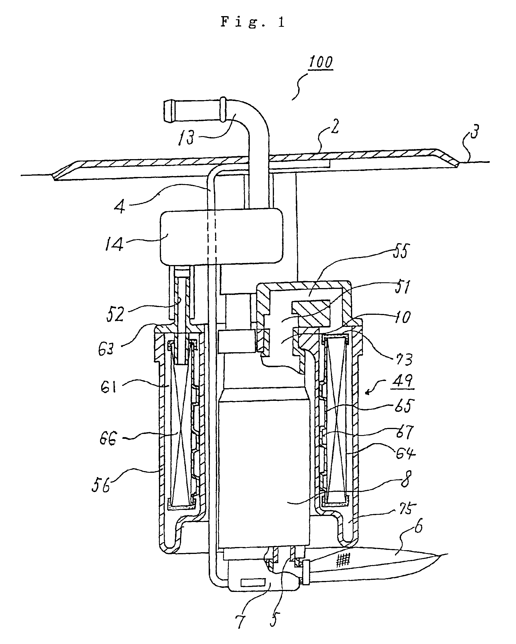
[0063]FIG. 1 is a sectional view showing a construction of a fuel supply system in which a fuel filter according to an Embodiment 1 of the present invention is used.

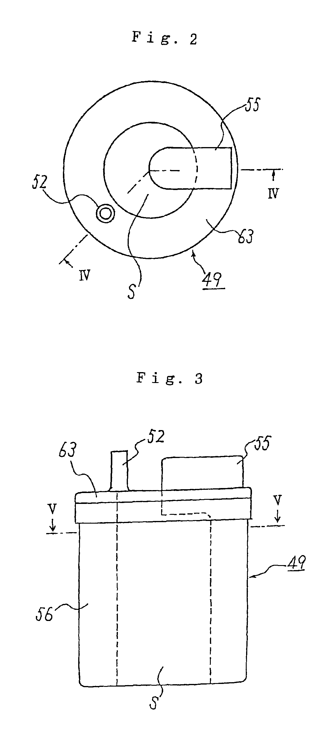
[0064]FIG. 2 is a top view of the fuel filter according to the Embodiment 1 shown in FIG. 1, and FIG. 3 is a side view of the fuel filter according to the Embodiment 1 shown in FIG. 1.

[0065]FIG. 4 is a sectional view take along the line IV—IV in FIG. 2, FIG. 5 is a sectional view take along the line V—V in FIG. 3 or the line V—V in FIG. 4, and FIG. 6 is an enlarged perspective view of an essential part of the fuel filter according to this embodiment shown in FIG. 1 or FIG. 4.

[0066]Referring to FIGS. 1 to 4, reference numeral 100 is a fuel supply system, numeral 2 is a fuel tank mounting plate, numeral 3 is a fuel tank, 4 is a bracket, 5 is a fuel pump suction port, 6 is a filter in the fuel tank (intank filter), 7 is a cover rubber, 8 is a fuel pump, 10 is a discharge port, 13 is a fuel feeding pipe, 14 is a check valve,...

embodiment 2

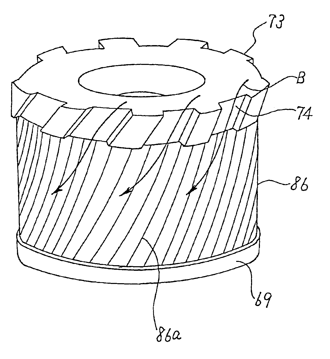
[0103]FIG. 7 is an enlarged perspective view of an essential part of a fuel filter according to an Embodiment 2 of the present invention.

[0104]In the drawing, reference numeral 69 is a lower end plate serving as a fixing member on the bottom part 60 side forming the filtration chamber 61, 73 is an upper end plate serving as a fixing member on the lid part 63 side (i.e., on the side where the fuel suction pipe 55 is disposed), 74 is an oblique passage formed on the outer circumferential face of the upper end plate 73, 86 is a filtering member made of nonwoven fabric with pleats-like folds, and numeral 86a is one of folds of the filtering member 86.

[0105]The arrows indicated by B show the flowing direction of fuel.

[0106]Likewise in the foregoing Embodiment 1, the upper end plate 73 provided with the oblique passage 74 for application of centrifugal force to the fuel sent into the filtration chamber 61 on its outer circumferential face is hereinafter referred to as centrifugal force ap...

embodiment 3

[0112]FIG. 8 is an enlarged perspective view of an essential part of a fuel filter according to Embodiment 3.

[0113]In the drawing, reference numeral 90 is a main container corresponding to the main container 56 of the fuel filter according to the foregoing Embodiment 1 or Embodiment 2, 91 is an outer cylinder serving as an outer wall of the main container 90 and forming the filtration chamber 61 not shown, and 92 is a spiral guide projection formed on the inner wall face of the outer cylinder 91.

[0114]Although the inner wall face of the outer cylinder 58 forming the filtration chamber 61 of the fuel filter is a substantially smooth face in the foregoing Embodiment 1 and Embodiment 2, the fuel filter according to this embodiment is characterized in that the spiral guide projection 92 inclined substantially in the same direction as the oblique passage 74 of the upper end plate 73 is additionally formed on the inner wall face of the outer cylinder 91 forming the filtration chamber 61.

[...


PUM

PropertyMeasurementUnit
centrifugal forceaaaaaaaaaa
circumferenceaaaaaaaaaa
suction forceaaaaaaaaaa

Abstract

A fuel filter includes: a filtration chamber consisting of an inner cylinder and an outer cylinder disposed concentrically with a predetermined space, a bottom part that closes an opening end on one end side of the inner cylinder and the outer cylinder, and a lid part disposed with a fuel suction pipe and a fuel sending pipe, that closes an opening end on the other end side of the inner cylinder and the outer cylinder; and a filtering member that is accommodated in a filtration chamber and filtrates fuel that flows into the filtration chamber. In this filter, a centrifugal force applying member for centrifuging the fuel that flows into is disposed at the end of the filtering member on the lid part side. A groove portion extending along an inner wall face of the outer cylinder is formed on the bottom part.

Description

[0001]This application is a continuation of PCT / JP02 / 01601 filed Feb. 8, 2003.TECHNICAL FIELD[0002]The present invention relates to a fuel filter used in a fuel supply system installed in, for example, a fuel tank of a vehicle and a fuel supply system using the fuel filter, and more particularly to a structure of a fuel filter for achieving extension of life and miniaturization.BACKGROUND ART[0003]FIG. 9 is a sectional view showing a construction of a fuel supply system in which a conventional fuel filter is used, which is disclosed in the Japanese Patent Publication (unexamined) No. 1998-43513, for example.[0004]In the drawing, reference numeral 1 is a fuel supply system, and a fuel tank mounting plate 2 is mounted on a fuel tank 3.[0005]A bracket 4 is welded to the fuel tank mounting plate 2, and the bracket 4 holds the vicinity of a cover rubber 7 and a filter in the fuel tank (intank filter) 6 attached to a fuel pump suction port 5 and supports a fuel pump 8.[0006]A fuel filter ...

Claims


Application Information

Patent Timeline
Patent Type & Authority Patents(United States)
IPC IPC(8): F02M37/04B01D29/90B01D35/027F02M37/10F02M37/34F02M37/44F02M37/50F04B23/02
CPCB01D29/906B01D35/0273F02M37/10F02M37/22B01D35/26B01D35/30B01D2201/291F02M2037/228F02M2037/225F02M37/44F02M37/50F02M37/34
Inventor YOSHIOKA, HIROSHI
Owner MITSUBISHI ELECTRIC CORP
Why Eureka
Try Eureka