Fuel delivery system for a combustion engine

a technology of fuel delivery system and combustion engine, which is applied in the direction of liquid fuel feeder, machine/engine, charge feed system, etc., can solve the problem of not being able to place a transfer line near or below the bottom of the two fuel tank chambers

Inactive Publication Date: 2006-07-04
TI GRP AUTOMOTIVE SYST LLC
View PDF13 Cites 56 Cited by
  • Summary
  • Abstract
  • Description
  • Claims
  • Application Information

AI Technical Summary

Benefits of technology

[0009]Objects, features and advantages of this invention include a vehicle having at least two fuel supply chambers with controlled fuel levels so that one fuel chamber does not empty before, or dominate over the other fuel chamber. Yet another advantage of the invention is the ability to use multiple, pre-existing, fuel pump modules to meet high fuel consumption demands of a large engine or multiple engines in a single vehicle, wherein one pump module is located in each fuel supply chamber. Other advantages include a more economical and robust fuel delivery system utilizing proven fuel pump modules, improved engine performance, improved vehicle handling, and a design which is relatively simple, economical to manufacture and assemble, and requires little to no maintenance and in service has a long useful life.
is the ability to use multiple, pre-existing, fuel pump modules to meet high fuel consumption demands of a large engine or multiple engines in a single vehicle, wherein one pump module is located in each fuel supply chamber. Other advantages include a more economical and robust fuel delivery system utilizing proven fuel pump modules, improved engine performance, improved vehicle handling, and a design which is relatively simple, economical to manufacture and assemble, and requires little to no maintenance and in service has a long useful life.

Problems solved by technology

Unfortunately, in some applications placing a transfer line near or below the bottom of the two fuel tank chambers is not practical due to surrounding vehicle structure or safety concerns.

Method used


Image

  • Fuel delivery system for a combustion engine
  • Fuel delivery system for a combustion engine
  • Fuel delivery system for a combustion engine

Examples


Embodiment Construction

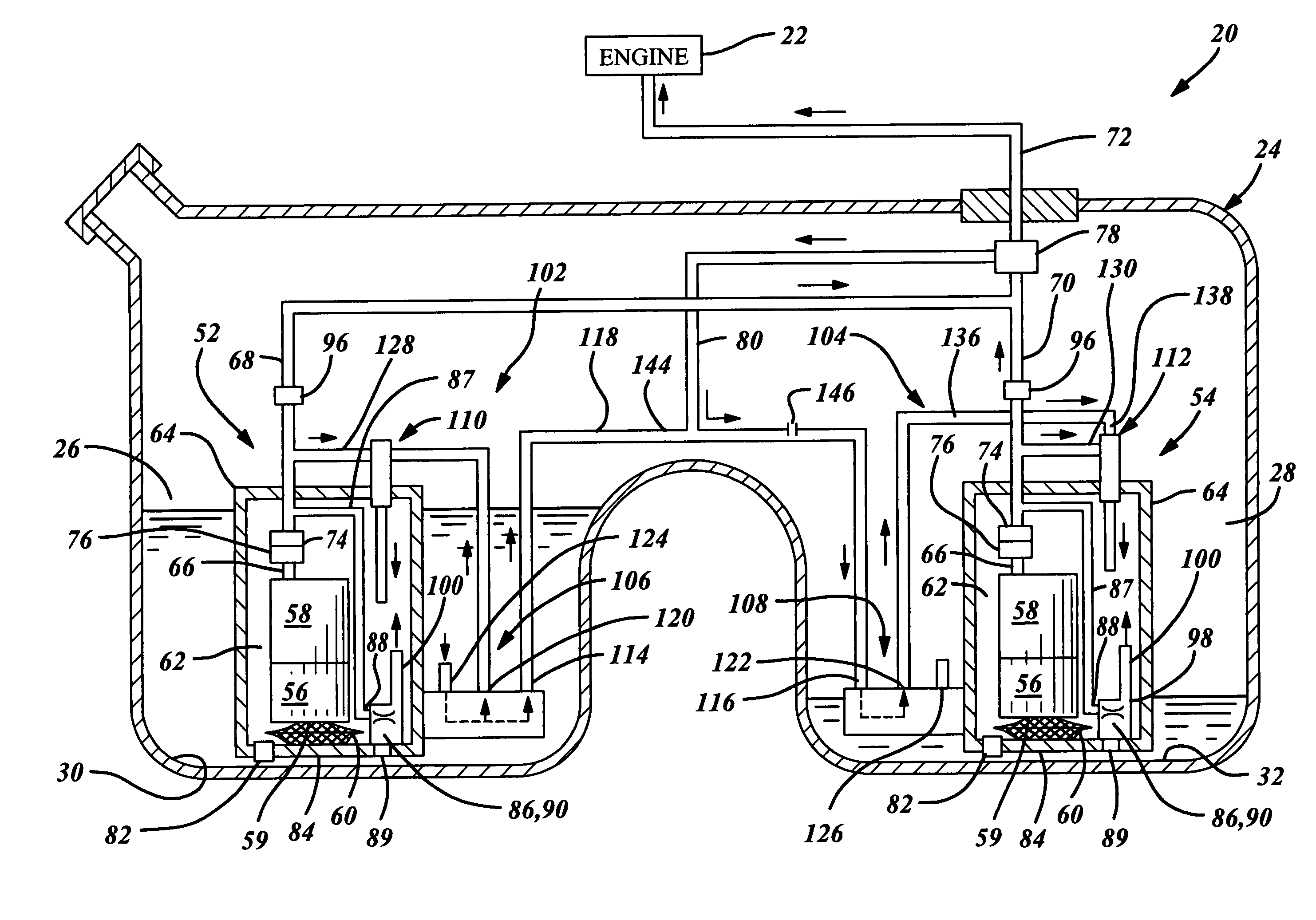
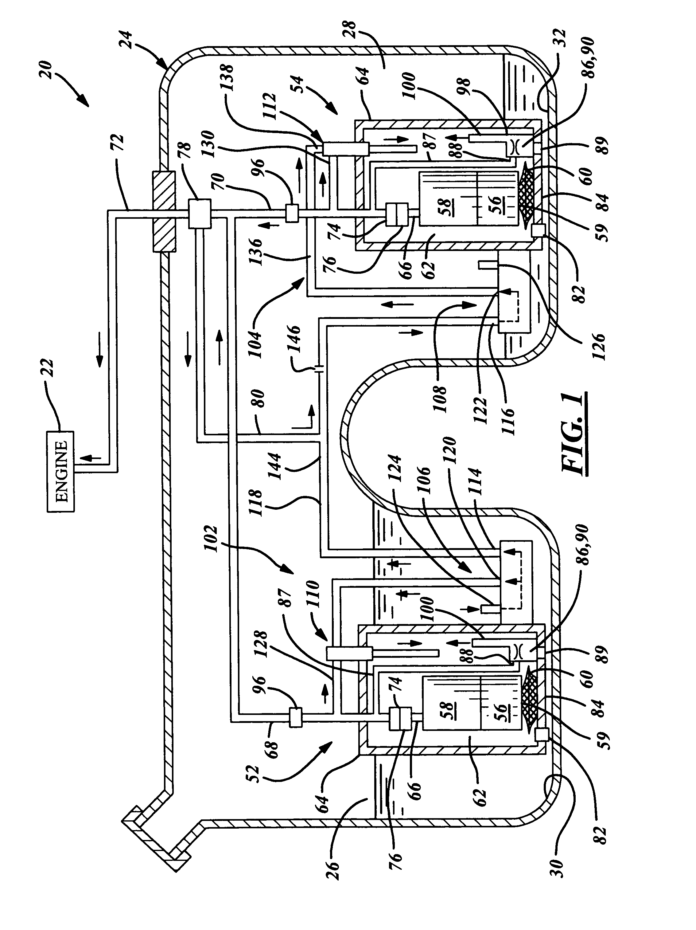
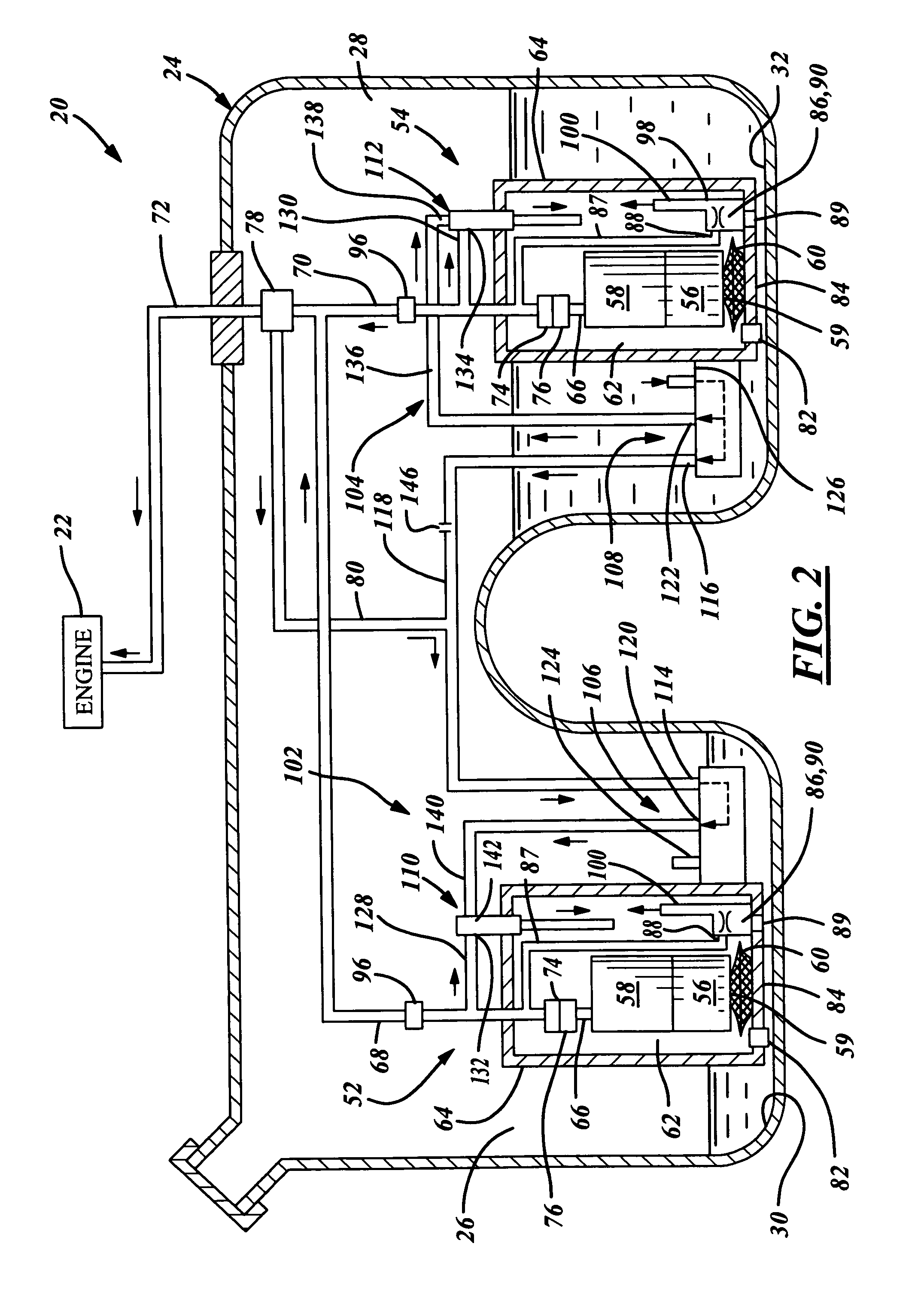
[0019]Referring in more detail to the drawings, FIGS. 1–4 illustrate a fuel delivery or supply system 20 for a combustion engine 22 which is preferably fuel injected. The fuel delivery system 20 has at least one fuel tank 24 which is preferably a saddle-tank typically used in rear-wheel-drive automotive vehicle applications. The at least one fuel tank 24 has a plurality of fuel chamber 26, 28 defined in-part by respective bottoms 30, 32. The plurality of fuel chambers, as illustrated, has a first fuel chamber 26 and a second fuel chamber 28, that generally communicate with one-another at an elevation which is substantially higher than the respective first and second bottoms 30, 32 for a number of practicality or structural reasons. Although the first and second fuel chambers 26, 28 are separated, the fuel delivery system 20 functions to maintain substantially equal or controlled fuel quantities or levels in each fuel chamber while meeting the fuel consumption demands of the at least...


PUM


Abstract

A fuel delivery system with at least one fuel tank and at least two fuel chambers has a fuel transfer assembly preferably integrated into an in-tank fuel pump module for controlling fuel levels between the at least two fuel chambers. The fuel transfer assembly has a transfer jet which receives pressurized fuel from a fuel pump of the module and at least two control valves for dictating the source of low pressure fuel flowing into the transfer jet and discharged therefrom preferably into a fuel reservoir of the module. Preferably, one control valve is located in each fuel chamber. The control valve opens upon a pre-established high fuel level and closes upon low fuel level. The fuel chamber containing the open control valve is generally the source of fuel for the fuel pump module.

Description

FIELD OF THE INVENTION[0001]This invention relates generally to a liquid fuel delivery system of a combustion engine for a vehicle and more particularly to at least one transfer jet pump assembly of the fuel system for controlling fuel levels between at least two fuel tank chambers.BACKGROUND OF THE INVENTION[0002]In transportation vehicles such as trucks, cars, planes and boats, the on-board fuel tank is generally shaped to maximize fuel storage capacity yet fit within often restricted areas dictated by the surrounding vehicle structure or chassis. Often, known saddle tanks or two distinct storage tanks having generally at least two separate fuel storage chambers are incorporated into the vehicle, see U.S. Pat. No. 5,170,764, to Tuckey and assigned to Walbro Corporation, issued Dec. 15, 1992, and incorporated herein by reference in it's entirety.[0003]Typically mounted in at least one of the two fuel chambers is an electric motor fuel pump commonly used to supply the fuel demand fo...

Claims


Application Information

Patent Timeline
Patent Type & Authority Patents(United States)
IPC IPC(8): F02M37/04
CPCF02M37/0052F02M37/18F02M37/025F02M37/106F02M37/0094F02M37/0029F02M37/0058
Inventor CRARY, LYNWOOD F.
Owner TI GRP AUTOMOTIVE SYST LLC
Why Eureka
Try Eureka