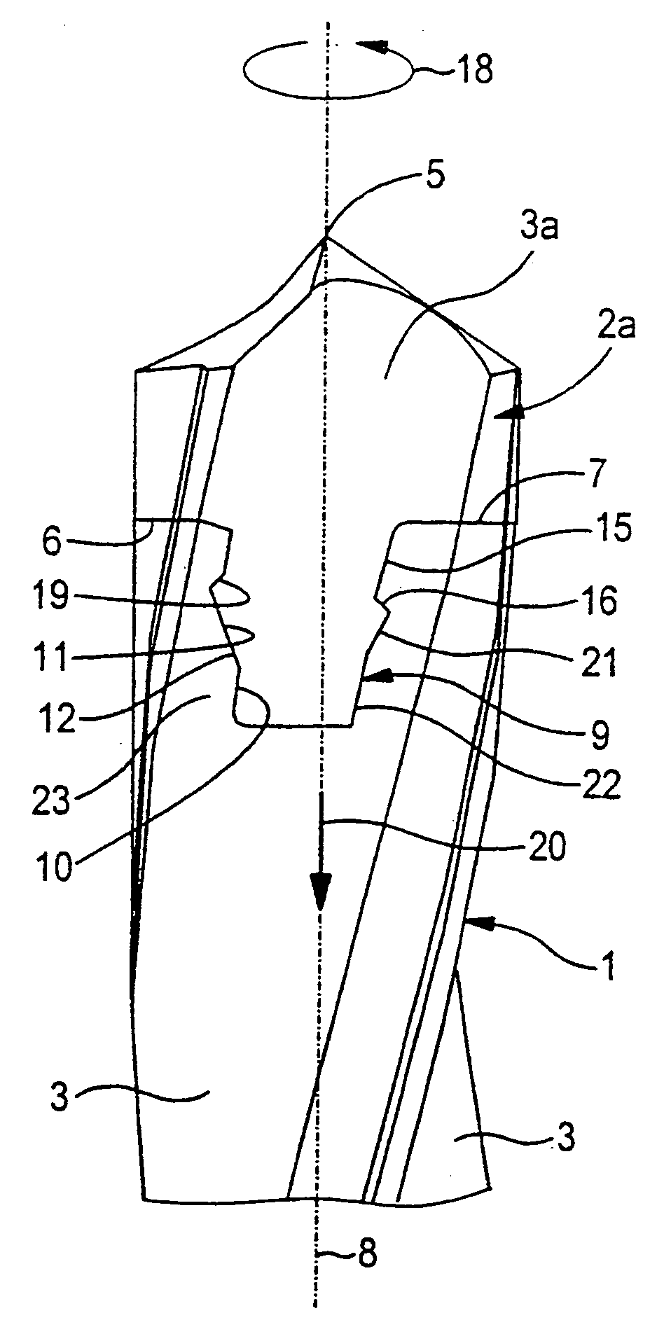
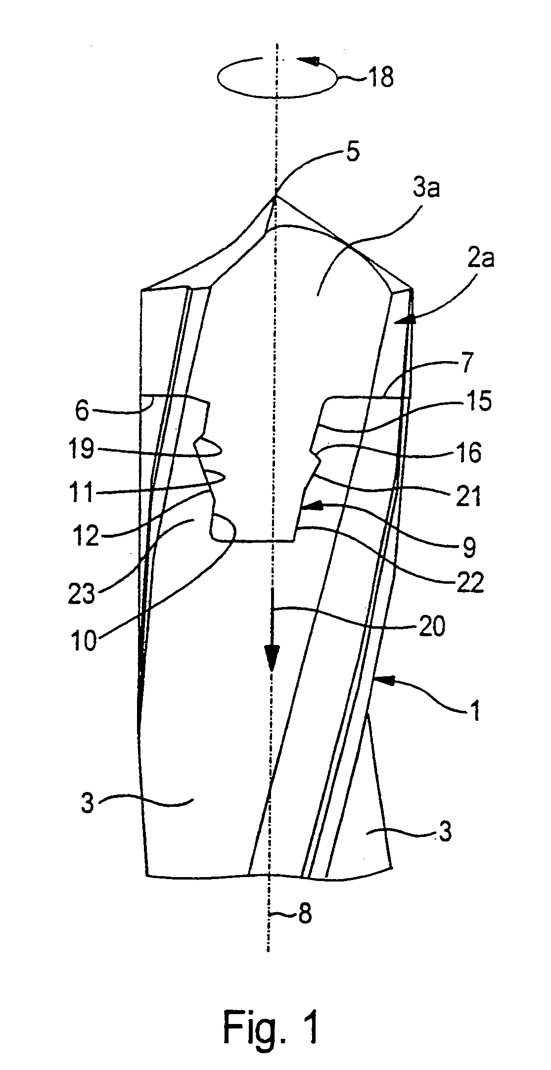
[0012]The cutting head is in contact with a
bearing surface against the face of the drill shaft, and extends by means a fixing stud that projects centrally out of the bearing surface into a complementary receiving recess in the face of the drill shaft. The
peripheral area of the fixing stud that interacts with the inner wall of the recess has two longitudinal segments, namely a first longitudinal segment which, with a screw surface that points toward the drill tip, slopes upward in the direction of rotation of the drill and interacts with an opposite surface on the inner wall of the receiving recess and merges into a second longitudinal segment. When the drill head is designed in this manner, it can be easily inserted with its fixing stud into the receiving recess and fixed in position opposite to the direction of rotation of the drill. The screw surface is thereby pushed onto the opposite surface of the receiving recess and the cutting head is pressed with its bearing surface onto the face of the drill shaft. This fixing is further strengthened when the drill is in operation.
[0013]In one preferred embodiment, the second longitudinal segment of the fixing stud tapers toward its free end. The receiving recess becomes narrower by the same extent toward its base. The shaft walls that are adjacent to the receiving recess can be correspondingly thicker and more stable in this area. The tool shaft is therefore more stable with regard to a force that is exerted on the cutting head at a right angle to the longitudinal axis of the drill than would be the case with a receiving recess that becomes wider toward its base in an approximately swallowtail shape. A particularly stable mounting and centering of the fixing stud in the receiving recess is essentially guaranteed if the free end of the fixing stud is provided with a cylindrical
peripheral surface and the area adjacent to it and extending to the screw surface is provided with a conical peripheral surface.
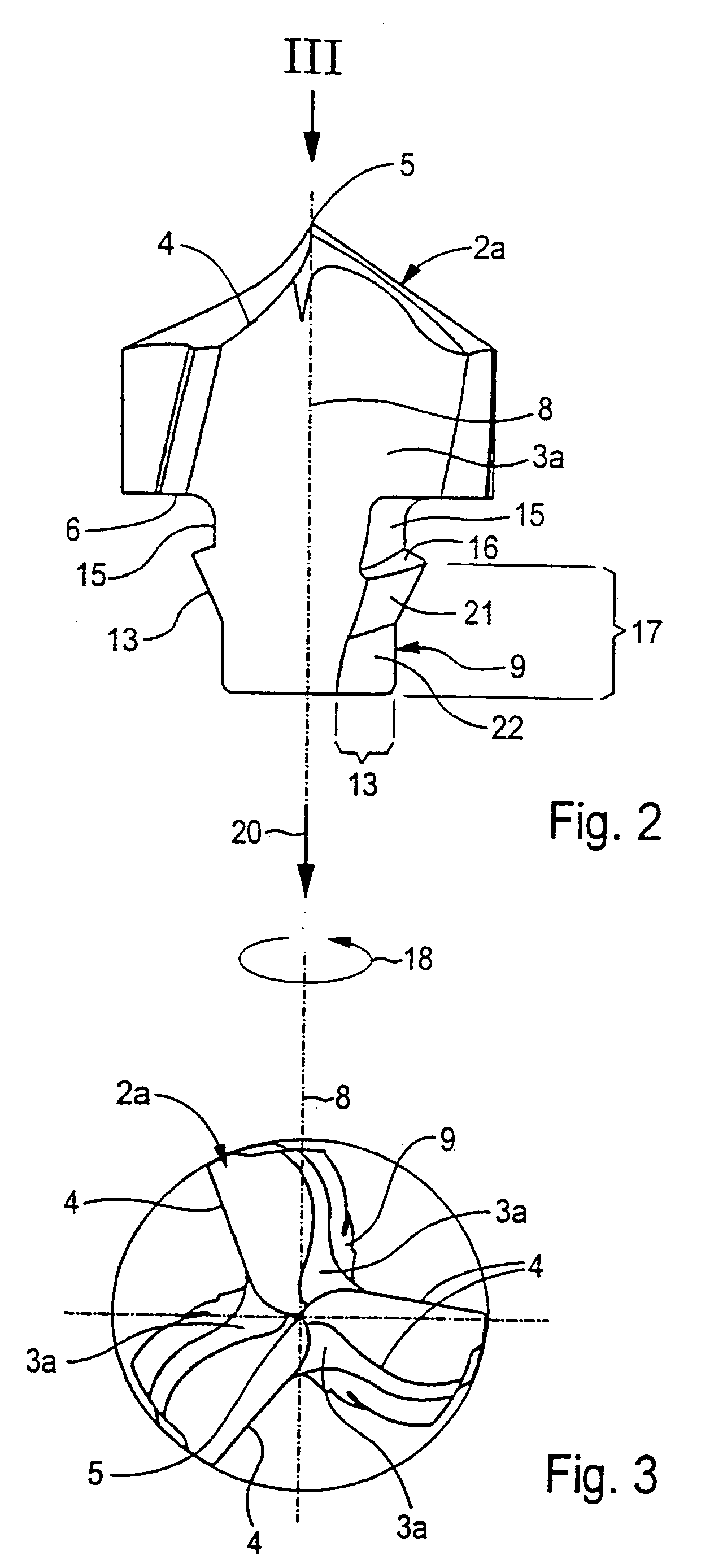
[0015]In at least one possible embodiment of the present invention, the surfaces of the fixing stud, as well as the surfaces of the drill bit shaft that engage with the surfaces of the fixing stud, can preferably be suitably designed to withstand torque and axial forces. During drilling of an object, torque forces are exerted on a drill. In addition, axial forces may
push and pull on the drill in the direction along the longitudinal axis of the drill, especially during retraction of the drill from an object being drilled. The peripheral segments of the fixing stud may therefore preferably be designed to withstand such forces since the peripheral segments may essentially perform a retaining function preferably to prevent the cutting insert from being pulled from the drill shaft during drilling. Conversely, in at least one possible embodiment of the present invention, the inner surfaces of the drill shaft may also be designed preferably to withstand the forces that are acting on the cutting insert to also substantially prevent the cutting insert from being pulled from the drill shaft. Further, since the cutting insert may essentially be screwed into place in the drill shaft in a direction opposite the direction of rotation of the drill, torque forces may be exerted on the cutting insert. According to at least one possible embodiment of the present invention, the inner surfaces of the drill shaft against which the sides of the cutting insert rest preferably must be suitably designed to essentially prevent the cutting insert from being further screwed into the shaft, which would most likely result in damage of the shaft and the insert. By strengthening the contact surfaces of the shaft and the cutting insert, the torque and axial forces can be substantially withstood to prevent damage to the drill.
[0016]In at least one other possible embodiment of the present invention, the
chip flutes of the drill bit may each be divided into essentially two portions: the portion of the
chip flute on the drill shaft and the portion of the
chip flute on the cutting insert. When the cutting insert is screwed into the drill shaft, the two chip flute portions can be aligned to form a
single chip flute surface. Although it may preferably be desirable to design the cutting insert and the drill shaft such that the chip flute portions are exactly aligned to form a chip flute that is substantially smooth and continuous, such a design may require high precision when manufacturing the cutting inserts and the drill shafts. It is well known, however, that any manufacturing process, no matter how precise, is subject to errors, tolerances and imperfections. It is therefore possible that the cutting inserts may not be precisely manufactured due to the inherent imperfections that occur during any manufacturing process. To account for such imperfections that may occur, in one possible embodiment of the present invention it may not be necessary to have precisely aligned chip flute portions. Since the chip flute portions may simply serve to remove chips, exact precision in their design may not be a requirement for proper operation of the drill. Further, the centering of the drill tip is often more important to a drilling process than the precise design of the chip flutes, since an off-center drill tip will often produce a wobbling motion of the drill during drilling, which is in many cases undesirable. The central fixing stud of the cutting insert can provide a centering function that essentially centers the drill tip along the central longitudinal axis of the drill bit. The present invention, in at least one possible embodiment, therefore teaches that as long as the drill tip of the cutting insert is designed to lie on the central longitudinal axis, it may be possible for the chip flute portions to be slightly misaligned without substantially affecting the performance of the drill.
[0017]Drills such as the type described above may be used, in at least one possible embodiment, to
cut various materials, such as metals, wood, plastics, composites, polymers, steel, and other hard materials. In addition, such drills may also possibly be used in
machine-operated, automatic drilling systems, such as numerically-controlled drilling systems on
assembly lines. By having replaceable cutting or drilling inserts, it may be possible in at least one possible embodiment of the present invention, to substantially maintain the overall length of the drill by replacing the cutting inserts when they become worn. By substantially maintaining the length of the drill, it may not be necessary to reconfigure or reprogram the machinery using the drill in the automatic drilling process since the drill will not substantially change in length.

