Fuel cell end unit with integrated heat exchanger

a fuel cell and heat exchanger technology, applied in the field of end plates and heat exchangers for fuel cell systems, can solve the problems of increasing the size and cost of the system, increasing the risk of cell-to-cell wet seal leakage, and non-uniform stack inlet temperature distribution

Inactive Publication Date: 2006-07-04
FUELCELL ENERGY INC
View PDF16 Cites 52 Cited by
  • Summary
  • Abstract
  • Description
  • Claims
  • Application Information

AI Technical Summary

Problems solved by technology

Also, in this type of system, process gas must be piped to and from the heat exchanger, adding to both the size and cost of the system.
Also, in this system, due to the inherent non-uniform temperature distribution at the outlet of the heat exchanger, the stack inlet temperature distribution is also non-uniform.
This condition is undesirable as non-uniform cathode inlet temperature not only creates a potential performance variation in the stack but also creates the risk of cell-to-cell wet seal leaks due to thermal expansion differences of the stack face.
The thin membrane structure is not specifically adapted to uniformly collect electrical current from the stack.
Again, this arrangement is not specifically adapted to provide uniform collection of electrical current.

Method used


Image

  • Fuel cell end unit with integrated heat exchanger
  • Fuel cell end unit with integrated heat exchanger
  • Fuel cell end unit with integrated heat exchanger

Examples


Embodiment Construction

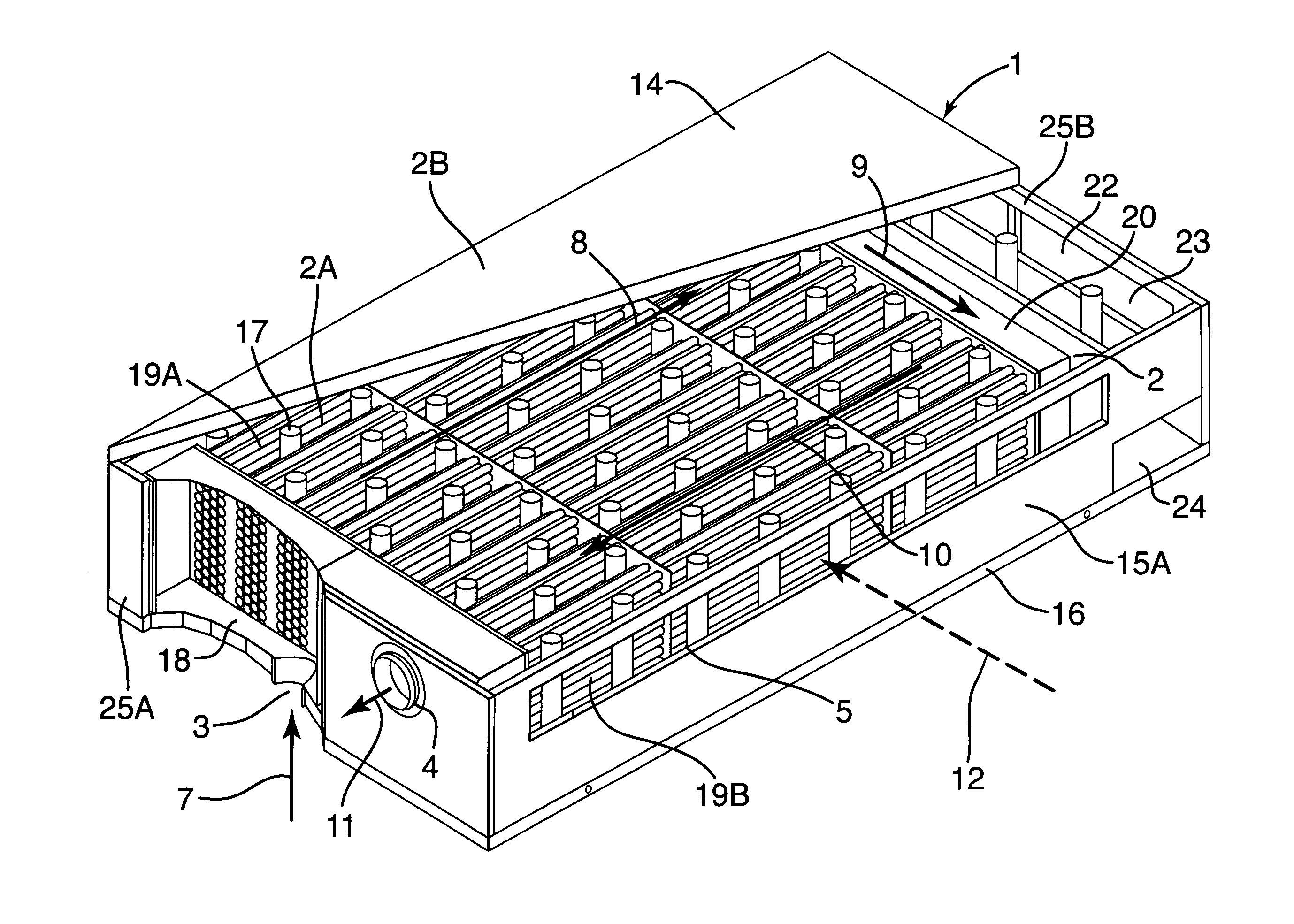
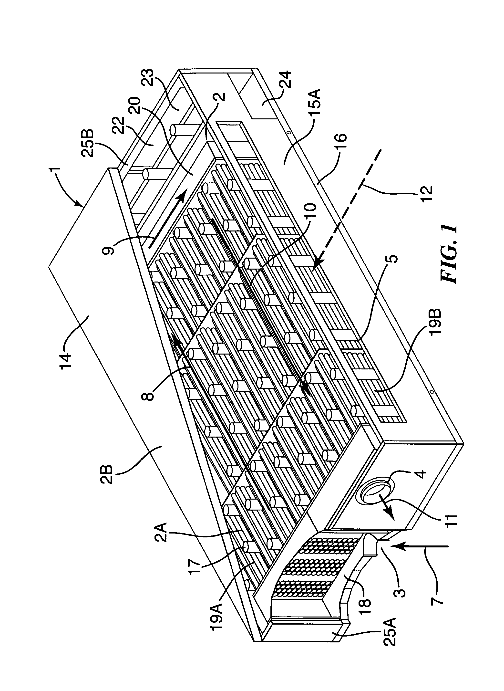
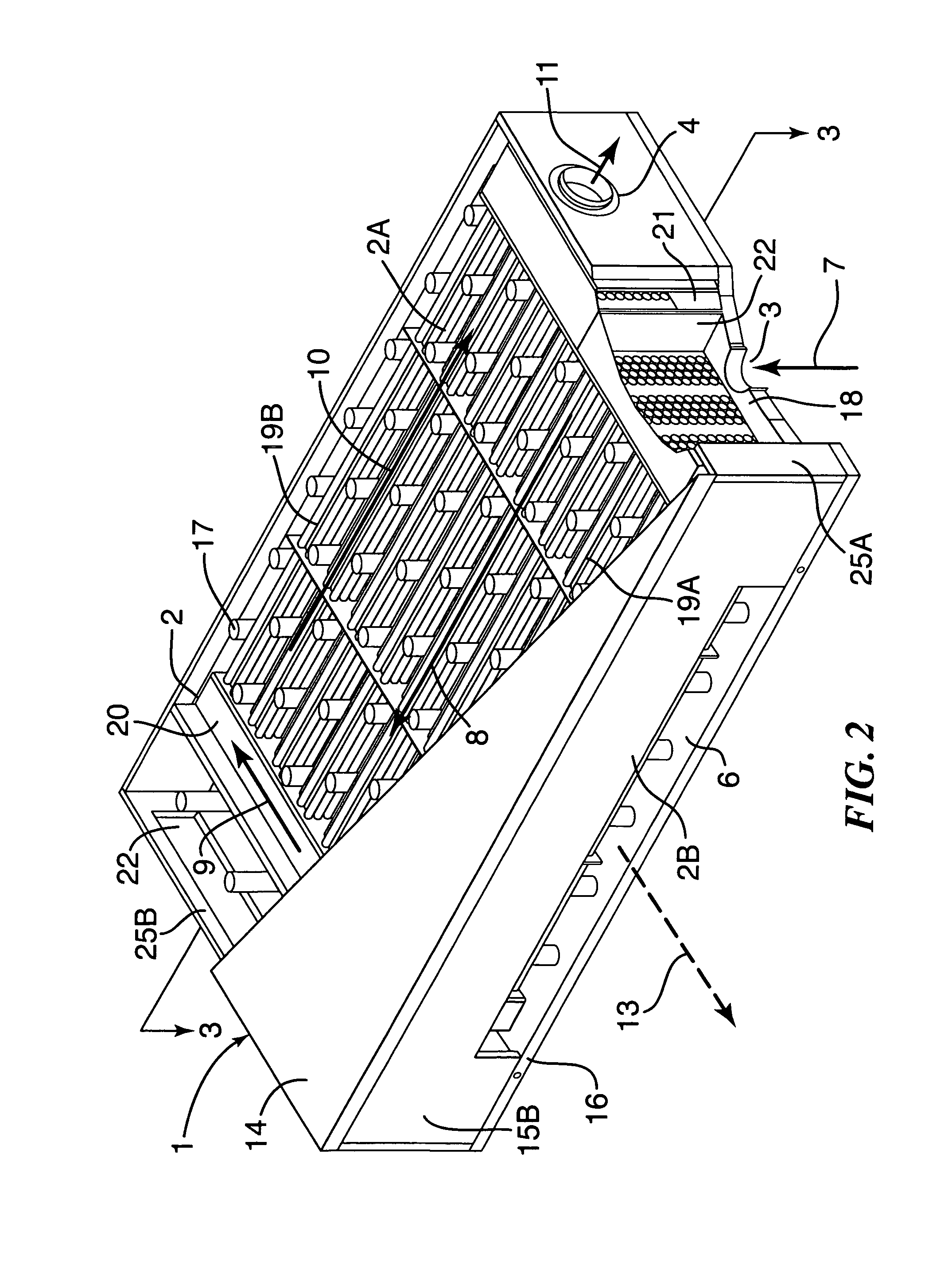
[0015]Referring to FIGS. 1, 2 and 3, the illustrative embodiment of the invention has an end unit 1 adapted to be attached to one end of a fuel cell stack. The end unit 1 houses an assembly 2 including first and second units 2A, 2B associated with the flow of a first and second gas, respectively, through the assembly and which act together as a heat exchanger. In the case shown, the first and second gases are fuel cell stack anode or fuel inlet gas and fuel cell stack cathode exhaust gas, respectively.

[0016]Particularly, the first unit 2A has an inlet 3 through which fuel gas passes (depicted by arrow 7) into an inlet chamber 18. Fuel gas collects in inlet chamber 18, flows in a direction 8 through a first set of tubes 19A and is delivered to a turn plenum 20. Fuel gas flows in a direction 9 through the turn plenum 20 and from the plenum 20 flows in a direction 10 through the tubes 19B. The gas is delivered by tubes 19B to an outlet chamber 21 (shown in FIGS. 2 and 3). Fuel gas exit...


PUM

PropertyMeasurementUnit
areaaaaaaaaaaa
thickaaaaaaaaaa
heataaaaaaaaaa

Abstract

An end unit for a fuel cell stack is described that contains an integrated heat exchanger for superheating the fuel gas before delivery to the stack. Heat is transferred from the hot cathode outlet stream to the cool fuel inlet stream in a space adjacent the stack's end plate. The end unit is designed as a hollow box forming the shell of the exchanger with the heat exchanger inside. The end unit has openings that allow fuel cell process gas to be taken directly from the stack without requiring piping or ductwork to be attached to thin manifolds. Separate chambers are provided for both the cathode outlet and anode outlet gas, thereby allowing all process connections to be made at one end of the stack. The end unit also features a current collection post that is separated from the end cell of the stack by a multitude of members which provide structural support for the end unit and act to more uniformly collect electrical current than would a single, large current post.

Description

BACKGROUND OF THE INVENTION[0001]This invention relates to fuel cells and, in particular, to end plates and heat exchangers for fuel cell systems. More specifically, this invention relates to highly integrated, compact heat exchangers for use in superheating fuel gas for high temperature fuel cells.[0002]A fuel cell is a device which directly converts chemical energy stored in a fuel such as hydrogen or methane into electrical energy by means of an electrochemical reaction. This differs from traditional electric power generating methods which must first combust the fuel to produce heat and then convert the heat into mechanical energy and finally into electricity. The more direct conversion process employed by a fuel cell has significant advantages over traditional means in both increased efficiency and reduced pollutant emissions.[0003]In general, a fuel cell, similar to a battery, includes a negative (anode) electrode and a positive (cathode) electrode separated by an electrolyte w...

Claims


Application Information

Patent Timeline
Patent Type & Authority Patents(United States)
IPC IPC(8): H01M8/04H01M8/24F28D7/00F28D7/06F28F9/00F28F9/22F28F19/00H01MH01M2/00H01M2/14H01M8/00
CPCH01M8/2415H01M8/04014H01M8/0247H01M8/0267Y02E60/50H01M8/2425H01M8/2457H01M8/2484H01M8/2485
Inventor BLANCHET, SCOTTPATEL, PINAKIN
Owner FUELCELL ENERGY INC
Why Eureka
Try Eureka