Low power balanced Colpitts oscillator with improved negative resistance

a low-power balanced, oscillator technology, applied in the field of oscillator circuits, can solve the problems of limiting the effectiveness or efficiency of the oscillator circuit, consuming more power of conventional oscillators, and limiting the use of standard phase locked loops, etc., to achieve the effect of improving negative resistance and low-power balanced colpitts

Active Publication Date: 2006-07-04
MICROCHIP TECH INC
View PDF2 Cites 4 Cited by
  • Summary
  • Abstract
  • Description
  • Claims
  • Application Information

AI Technical Summary

Benefits of technology

[0008]To achieve these and other advantages and in order to overcome the disadvantages of the conventional method in accordance with the purpose of the invention as embodied and broadly described herein, the present invention provides a low power balanced Colpitts oscillator with improved negative resistance.
[0009]The low power balanced oscillator circuit comprises a crystal oscillator connecting two cross-coupled Colpitts oscillators. The oscillators are cross-coupled by either a direct connection or by capacitors. The crystal oscillator provides the Colpitts oscillators with a reference frequency that is half a duty cycle out of phase for each Colpitts oscillator. In this way, the oscillator circuit effectively doubles the reference frequency.
[0010]A single current source can be used for both Colpitts oscillators. In contrast, if two current sources were used they would both be constantly active even though it isn't necessary whenever their respective Colpitts transistor is turned on. When one Colpitts transistor is on, the current source connected to the opposite transistor could in effect be turned off. Additionally, a transistor in each Colpitts oscillator can act as a switch that is controlled by the opposite Colpitts transistor's gate voltage due to cross-coupling the two Colpitts oscillators. Therefore efficient operation can be achieved by using a single current source, which reduces the current and power consumption in half.
[0012]Furthermore, the sources of the transistors acting as current sources can be connected to ground. Grounding this node further improves the small loop gain and directly improves the absolute value of the negative resistance.
[0013]As a result, the present invention provides an efficient and effective oscillator with low power consumption and improved negative impedance.

Problems solved by technology

As frequency requirements continue to rise, stability and phase noise performance become issues that can limit the effectiveness or efficiency of the oscillator circuit.
In applications where phase noise and jitter sensitivity is of concern, standard phase locked loops are typically not usable.
Additionally, conventional oscillators can consume more power than is ideal for a low power consumption device.

Method used


Image

  • Low power balanced Colpitts oscillator with improved negative resistance
  • Low power balanced Colpitts oscillator with improved negative resistance
  • Low power balanced Colpitts oscillator with improved negative resistance

Examples


Embodiment Construction

[0019]Reference will now be made in detail to the preferred embodiments of the present invention, examples of which are illustrated in the accompanying drawings. Wherever possible, the same reference numbers are used in the drawings and the description to refer to the same or like parts.

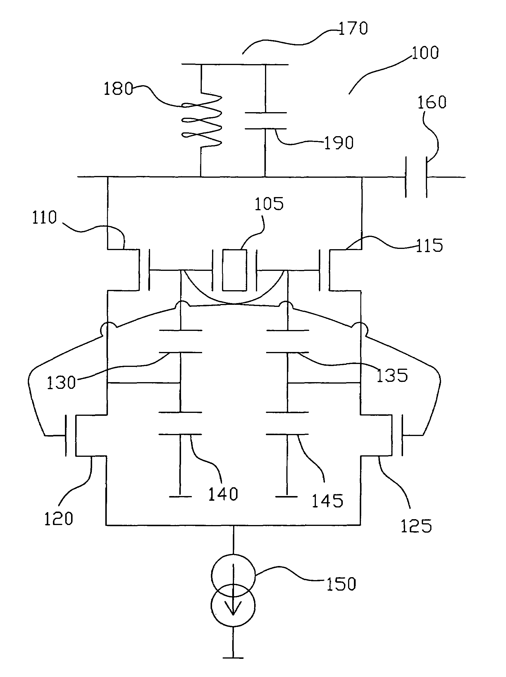
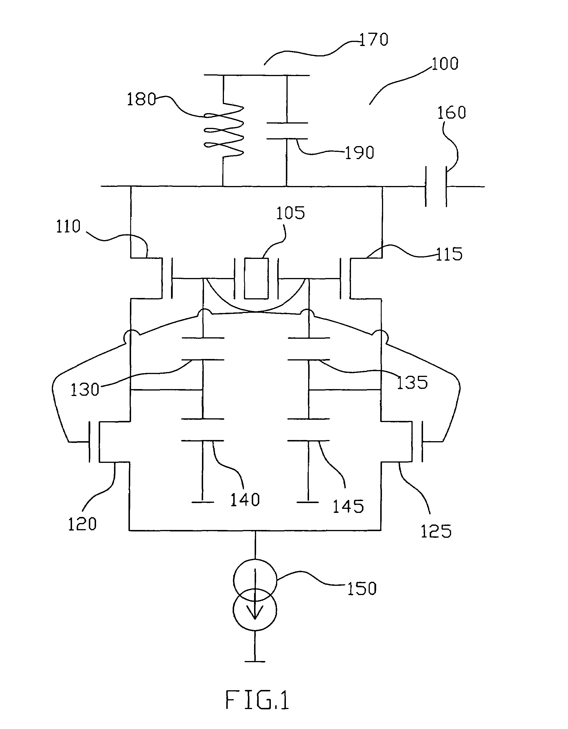
[0020]Refer to FIG. 1, which is a circuit schematic of low power balanced Colpitts oscillator according to an embodiment of the present invention.

[0021]As shown in FIG. 1, the low power balanced Colpitts oscillator 100 comprises a crystal oscillator 105 electrically connected between the gates of a first transistor 110 and a third transistor 115. A first capacitor 130 is connected between the gate and the source of the first transistor 110. A second capacitor 140 is connected between the source of the first transistor 110 and ground. The drain of a second transistor 120 is connected to the source of the first transistor 110.

[0022]A third capacitor 135 is connected between the gate and the source of t...


PUM


Abstract

A low power balanced Colpitts oscillator circuit with improved negative resistance. The oscillator circuit comprises two cross-coupled Colpitts oscillators with a crystal oscillator connected between the two oscillators. A single current source can be used for both Colpitts oscillators since only one Colpitts needs a current source at a time. Using a single current source cuts the power consumption in half. Alternatively, a transistor in each Colpitts oscillator can act as a current source, which is turned on or off depending on the state of the Colpitts transistor. The two current sources are biased at a common level and matched to ensure the circuit remains symmetrical. An additional benefit of the present invention is that the negative resistance is directly improved.

Description

BACKGROUND OF THE INVENTION[0001]1. Field of the Invention[0002]The present invention relates to an oscillator circuit. More specifically, the present invention discloses a low power balanced Colpitts oscillator with improved negative resistance.[0003]2. Description of the Prior Art[0004]Oscillator circuits are used for providing a reference frequency for other circuits or components in a system. As frequency requirements continue to rise, stability and phase noise performance become issues that can limit the effectiveness or efficiency of the oscillator circuit. This in turn directly affects the other circuitry utilizing the frequency signal.[0005]In applications where phase noise and jitter sensitivity is of concern, standard phase locked loops are typically not usable. In these applications, non-PLL circuits are required.[0006]Additionally, conventional oscillators can consume more power than is ideal for a low power consumption device.[0007]Therefore, there is need for an effici...

Claims


Application Information

Patent Timeline
Patent Type & Authority Patents(United States)
IPC IPC(8): H03B5/36
CPCH03B5/36
Inventor GUEBELS, PIERRE PAUL
Owner MICROCHIP TECH INC
Why Eureka
Try Eureka