Color display device

a color display and display device technology, applied in the field of color display devices, can solve the problems of inability to achieve luminance more than 100%, inability to widen the color reproduction range of primary colors by controlling signal processing, and excessive reduction of chroma (color purity)

Inactive Publication Date: 2006-07-04
SHARP KK
View PDF11 Cites 8 Cited by
  • Summary
  • Abstract
  • Description
  • Claims
  • Application Information

AI Technical Summary

Benefits of technology

[0005]However, in the invention of Japanese Unexamined Patent Publication No. 240198/1998, since the chromaticity adjustment circuit raises gradation values of the one or two signals having smaller gradation values, the color reproduction range (chromaticity range) of c

Problems solved by technology

Further, the invention of the Japanese Unexamined Patent Publication No. 240198/1998 made it possible to adjust the color reproduction range; however, in a color liquid crystal display device, it is not possible to widen the color reproduction range of primary colors by controlling signal processing.
This is because it is not possible to obtain luminance of more than 100% with respect to each pixel by controlling signal processing.
Meanwhile, in a shutter type color display such as a liquid crystal display, generally, light is not fully shaded by a light shutter, and chroma (color purity) is excessively reduced at a dark gradation because of the leakage of light.
In this type of display devices, transmittance conflicts with color purity.
Further, a projection type color display, a color electroluminescence display, a color plasma display and a color field emission display, which are lately receiving much public att

Method used


Image

  • Color display device
  • Color display device
  • Color display device

Examples


embodiment 1

[Embodiment 1]

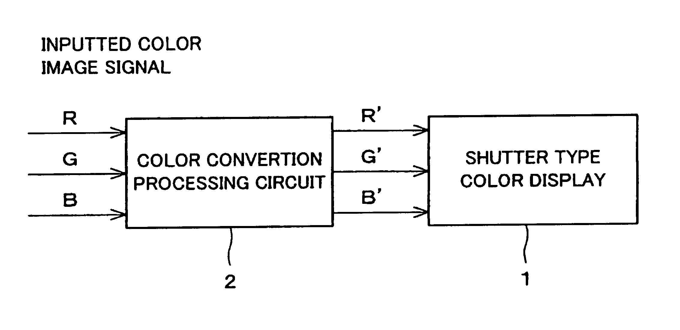
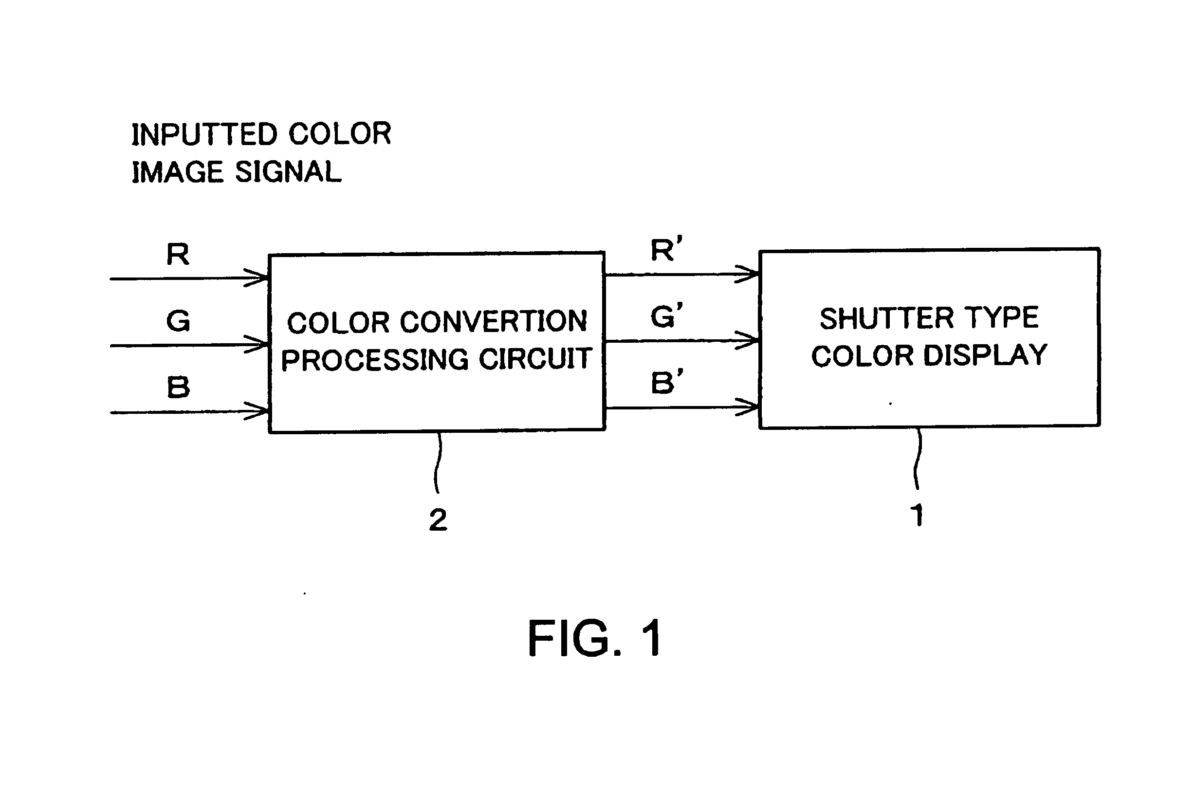
[0065]The following will explain one embodiment of the present invention with reference to FIG. 1.

[0066]As shown in FIG. 1, a color display device of the present embodiment includes:

[0067]a shutter type color display 1 which adjusts light from a light source, such as the sun or room lighting, according to a color image signal so as to display an image;

[0068]a color conversion processing circuit (signal processing means, color conversion processing means) 2 which processes a color image signal made up of a red signal indicating gradation levels of red, a green signal indicating gradation levels of green, a blue signal indicating gradation levels of blue, then outputs the converted color image signal including the red signal, the green signal and the blue signal to the shutter type color display 1.

[0069]When the gradation levels of R, G, and B of the inputted color image signal are not equal, the color conversion processing circuit 2 increases the gradation level of the ...

embodiment 2

[Embodiment 2]

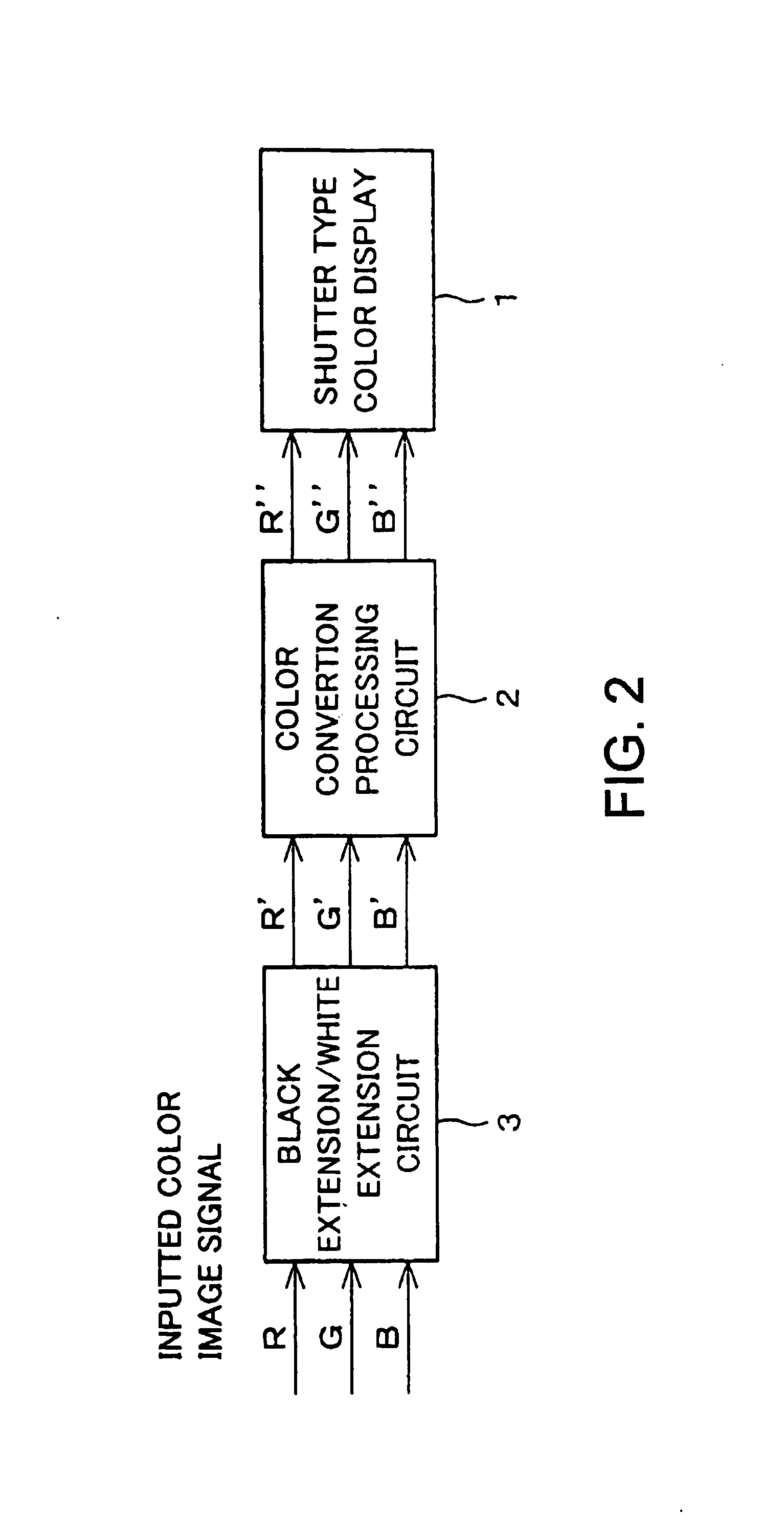
[0077]The following will explain another embodiment of the present invention with reference to FIG. 2. For ease of explanation, materials having the equivalent functions as those shown in the drawings pertaining to Embodiment 1 above will be given the same reference symbols, and explanation thereof will be omitted here.

[0078]As shown in FIG. 2, a color display device of the present embodiment is the same as that of Embodiment 1 except for an additionally provided black extension and white extension circuit (signal processing means, black extension and white extension means) 3.

[0079]The performance of the color conversion processing circuit 2 is also the same as that of the first embodiment except for its signal processing with respect to a color image signal outputted from the black extension and white extension circuit 3 instead of processing an inputted color image signal. Namely, the color conversion processing circuit 2 converts the values r′, g′ and b′, which are ...

embodiment 3

[Embodiment 3]

[0088]The following will explain another embodiment of the present invention with reference to FIG. 3. For ease of explanation, materials having the equivalent functions as those shown in the drawings pertaining to the first and second embodiments above will be given the same reference symbols, and explanation thereof will be omitted here.

[0089]As shown in FIG. 3, a color display device of the present embodiment is the same as that of Embodiment 2 except for an external light sensor (sensing means) 4 for sensing brightness of external light, and a color conversion adjuster (adjustment means) 5, which are additionally provided.

[0090]The color conversion processing circuit 2 converts the values r′, g′ and b′, which are the gradation values of the color signals of R′, G′ and B′ outputted from the black extension and white extension circuit 3, to the values r″, g″ and b″ which are the gradation values calculated by the following equations.

(Note; when a calculation result i...


PUM


Abstract

A color display device includes a shutter type color display and signal processing means. The signal processing means has color conversion processing means for increasing a gradation level of a color signal having the highest gradation level while decreasing a gradation level of a color signal having the lowest gradation level when the gradation levels of the plural color signals are not equal one another, and for outputting a color signal has been processed to the shutter type color display. Further, a color display having a reflective member or a diffuse transmission member provided on a display screen or in the vicinity of the display screen, a color plasma display, or a color field emission display can also be used instead of the shutter type color display. Thus, even when chroma of the color display is low, a display in high chroma can be ensured.

Description

FIELD OF THE INVENTION[0001]The present invention relates to a color display device including signal processing means, and in particular to a color display device including: a shutter type color display, a color display having a reflective member or a diffuse transmission member provided on a display screen or in the vicinity of the display screen, a color plasma display, or a color field emission display; and color conversion means for improving chroma.BACKGROUND OF THE INVENTION[0002]In recent years, color liquid crystal display devices having various types of signal processing circuits have been developed in order to improve image quality, particularly for a liquid crystal television.[0003]For example, Japanese Unexamined Patent Publication No. 10-240198 / 1998 (Tokukaihei 10-240198 published on Sep. 11, 1998) discloses a color liquid crystal display device including a chromaticity adjustment circuit. When one or two of signals of a red image display digital signal (R signal), a gr...

Claims


Application Information

Patent Timeline
IPC IPC(8): G09G5/10G06T1/00G06T5/00G09G3/20G09G3/22G09G3/28G09G3/36G09G5/02H04N9/31H04N9/64
CPCG09G3/2007H04N9/3197H04N9/3182G09G5/02G09G2320/0276G09G3/36
Inventor MIYACHI, KOICHIJINDA, AKIHITOMIYATA, HIDEKAZUTOMIZAWA, KAZUNARISHIOMI, MAKOTO
Owner SHARP KK
Why Eureka
Try Eureka