Fluorescence reference plate

a fluorescence reference plate and reference plate technology, applied in the field of multimodality fluorescence reference plates, can solve the problems of inability to readily apply methods to hts and the use of micro-well plates, time-consuming and prone to errors, and excessive wear of fluorogenic coatings

Active Publication Date: 2006-07-04
GE HEALTHCARE LTD
View PDF7 Cites 73 Cited by
  • Summary
  • Abstract
  • Description
  • Claims
  • Application Information

AI Technical Summary

Benefits of technology

[0026]Suitably, the fluorogenic compound consists of stable, non-radioactive atoms. The use of non-radioactive atoms avoids any restrictions being placed upon the use of the plate in terms of operator safety, handling and transport.

Problems solved by technology

This method, however, is not readily applicable to HTS and the use of micro-well plates.
Such an operation can be both time-consuming and prone to errors.
Furthermore, the continued handling of the probes can lead to excessive wear of the fluorogenic coating with a resultant reduction in fluorescent signal.
The preparation of such plates can be time-consuming to ensure that the fluorophore is fitted evenly into the well or trough.
Such materials do not lend themselves readily for calibrating PMT fluorimeters and CCD-based imaging systems.
With only twelve wells capable of generating a signal, the calibration microplate has little utility as a reference standard for CCD-based imaging systems.
The manufacturing process, however, imposes certain restrictions on the product in terms of cost and the availability of only those dyes that are soluble in organic solvents.
Due to the radioactive nature of the inorganic standard, it may be necessary to apply certain safety restrictions when handling or using these plates.
Furthermore, the number of reference standards are restricted to those ‘inorganic standards’ commercially available.

Method used


Image

  • Fluorescence reference plate
  • Fluorescence reference plate
  • Fluorescence reference plate

Examples


examples

[0069]The following example are illustrative of certain preferred embodiments of the instant invention but are not intended to be illustrative of all embodiments.

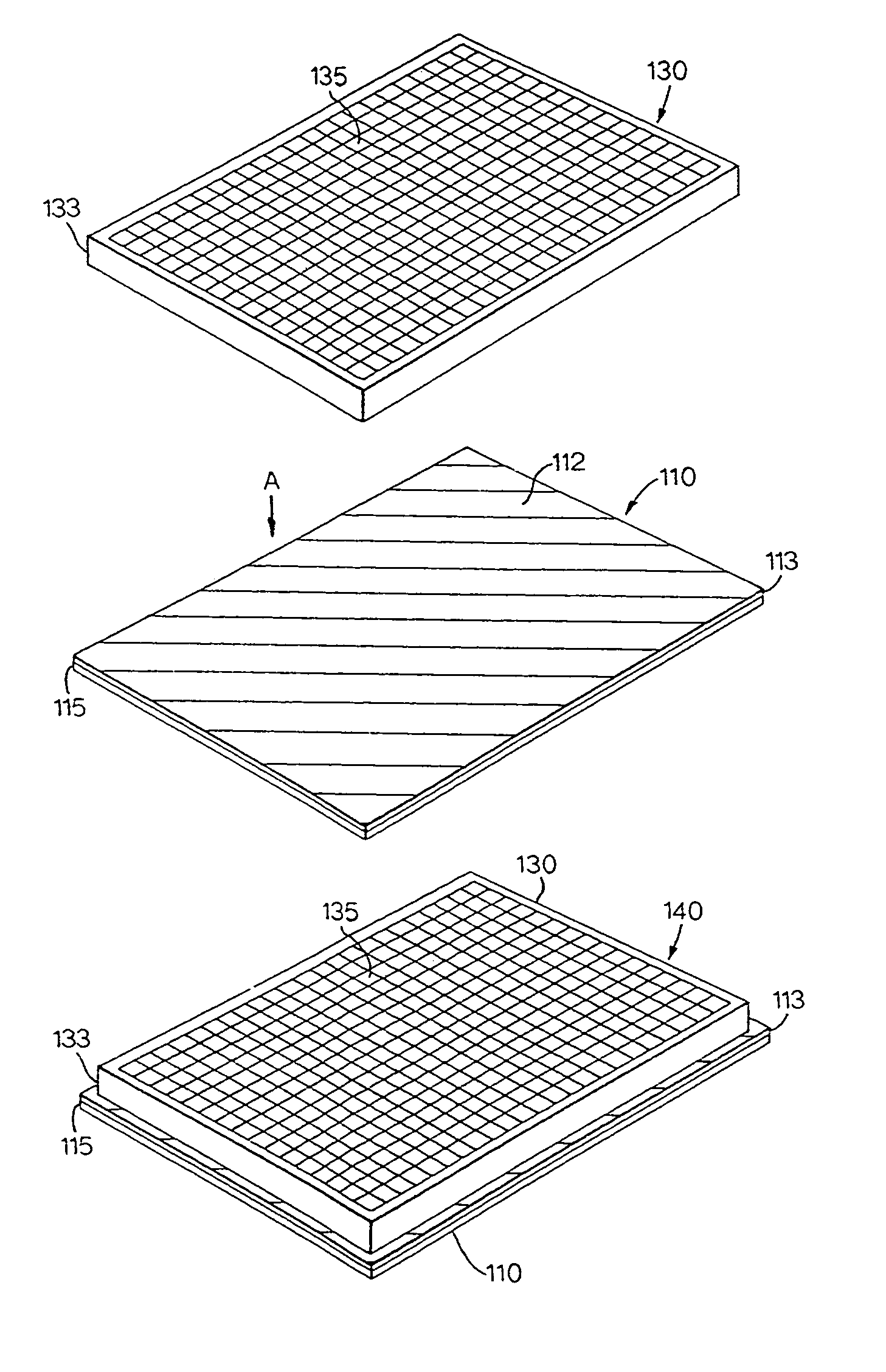
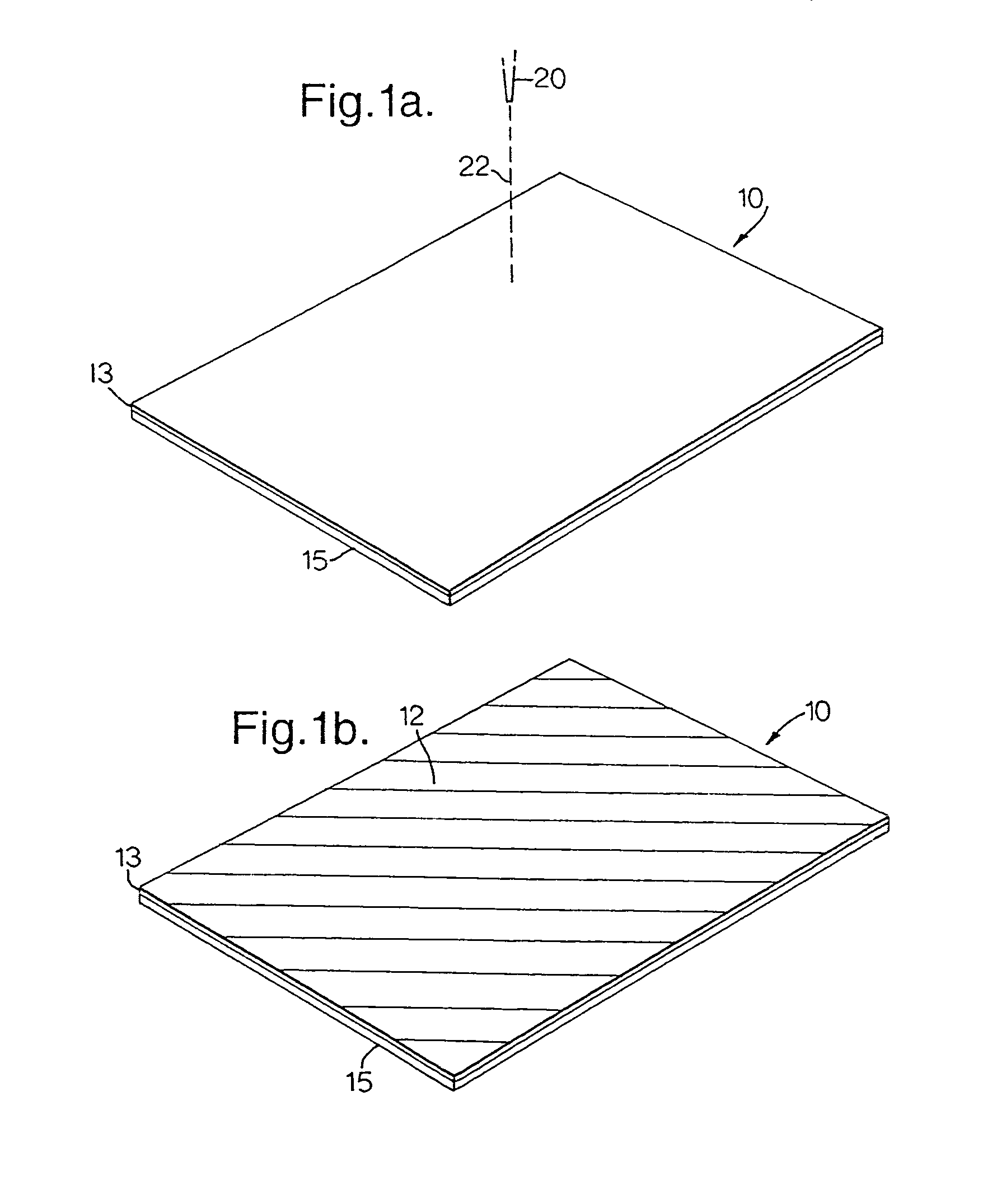
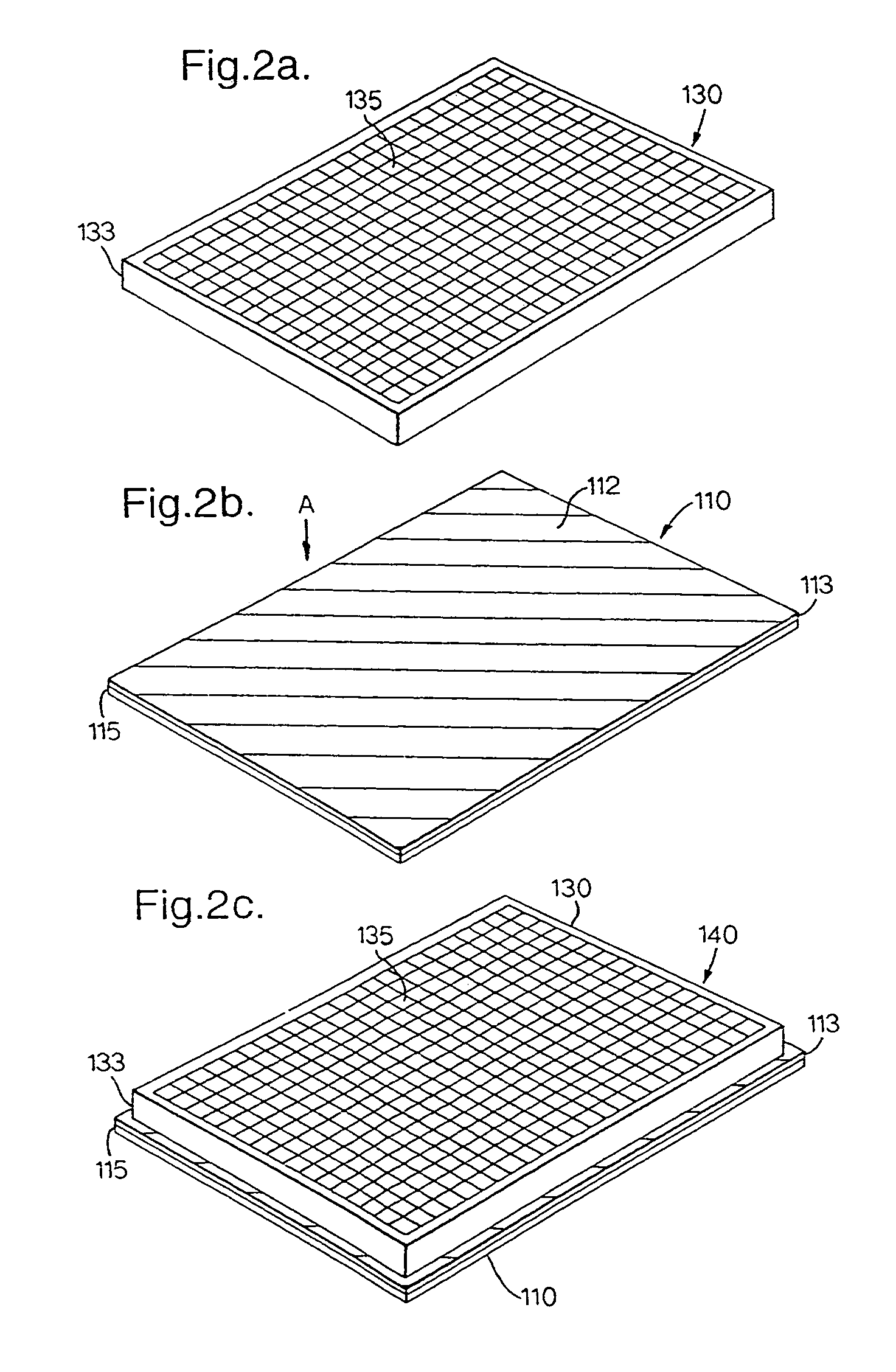
[0070]Typical fluorescence results from a reference plate made according to the present invention are shown in Table 1. The fluor Cy3 was dissolved in an aqueous printing ink base (Coates Brothers plc, Bath, UK) to give a concentration of 10 μM. The solution was added to a Canon BCI-21 ink jet cartridge and inserted into a standard Canon S100 printer. A uniform coating of Cy3 was then applied to a base sheet, comprising ‘Silver Glossy Film’, by ink jet printing and a 384 well reference plate constructed as described in FIGS. 3a–c above.

[0071]Fluorescence intensity readings of all 384 wells were taken using an excitation wavelength of 558 nm with a Leadseeker™ imaging system. The average intensity is shown in Table 1 below. As can be seen, the coefficient of variation obtained is exceedingly low, highlighting the accuracy an...


PUM

PropertyMeasurementUnit
volumesaaaaaaaaaa
volumesaaaaaaaaaa
excitation wavelengthaaaaaaaaaa

Abstract

A multi-modality fluorescence reference plate comprising wells coated with a fluorogenic compound is described, together with a method of producing such a plate. The plate has utility for calibrating fluorescent plate readers and imaging systems for measuring steady-state fluorescence, time-resolved fluorescence, fluorescence lifetime and/or fluorescence polarisation.

Description

BACKGROUND OF THE INVENTION[0001]The present invention relates to a multi-modality fluorescence reference plate useful for calibrating and testing fluorescence spectroscopic instruments, such as microscopes, imaging devices and plate readers. The invention also relates to a method of manufacturing such plates and to the use of the plates in steady-state fluorescence, time-resolved fluorescence, fluorescence polarisation and fluorescence lifetime.[0002]Many dye molecules, when irradiated with visible or ultraviolet light, emit a portion of the absorbed energy as fluorescent light at longer wavelength. These dye molecules, known as fluorogenic compounds, are widely used in biological assays, where the fluorescent signals they produce can provide information about the system under study. The technique of fluorometry is extremely powerful, since it provides an extremely sensitive measurement on very small quantities of materials under study.[0003]Fluorometers have three principal compon...

Claims


Application Information

Patent Timeline
Patent Type & Authority Patents(United States)
IPC IPC(8): G01N21/01G01N1/10B01L3/00G01N21/27G01N21/64
CPCG01N21/64G01N21/278B01L3/5085
Inventor JONES, CHRISTOPHER NICHOLASMEYLER, PHILIP JOHNJESSOP, ROBERT ARNOLDHATCHER, MALCOLM JOHNPAGE, MICHAEL KEITHLOOKER, MICHAEL ROGER
Owner GE HEALTHCARE LTD
Why Eureka
Try Eureka